Supercharge Your Innovation With Domain-Expert AI Agents!

Hydraulic pump control valve

A hydraulic pump and control valve technology, which is applied in the field of hydraulic pump manufacturing, can solve the problems of increased frictional resistance, high processing cost, and stagnation, and achieve the effects of reduced frictional resistance, low processing cost, and fewer parts

Pending Publication Date: 2018-03-09
JIANGSU HENGLI HYDRAULIC TECH CO LTD
View PDF0 Cites 3 Cited by
  • Summary
  • Abstract
  • Description
  • Claims
  • Application Information

AI Technical Summary

Problems solved by technology

When the existing hydraulic pump control valve is working, the guide rod between the push rod of the electromagnet and the spool of the control valve is prone to stagnation, which increases frictional resistance and causes hysteresis in the control valve.
Moreover, the existing hydraulic pump control valve has complex structure, many parts and high processing cost

Method used


Image

  • Hydraulic pump control valve
  • Hydraulic pump control valve
  • Hydraulic pump control valve

Examples


Embodiment Construction

[0051] In order to make the objectives, technical solutions, and advantages of the embodiments of the present invention clearer, the technical solutions of the embodiments of the present invention will be described clearly and completely in conjunction with the accompanying drawings of the embodiments of the present invention. Obviously, the described embodiments are part of the embodiments of the present invention, rather than all of the embodiments. Based on the described embodiments of the present invention, all other embodiments obtained by a person of ordinary skill in the art fall within the protection scope of the present invention.

[0052] The hydraulic pump control valve 1000 according to an embodiment of the present invention will be described in detail below with reference to the accompanying drawings.

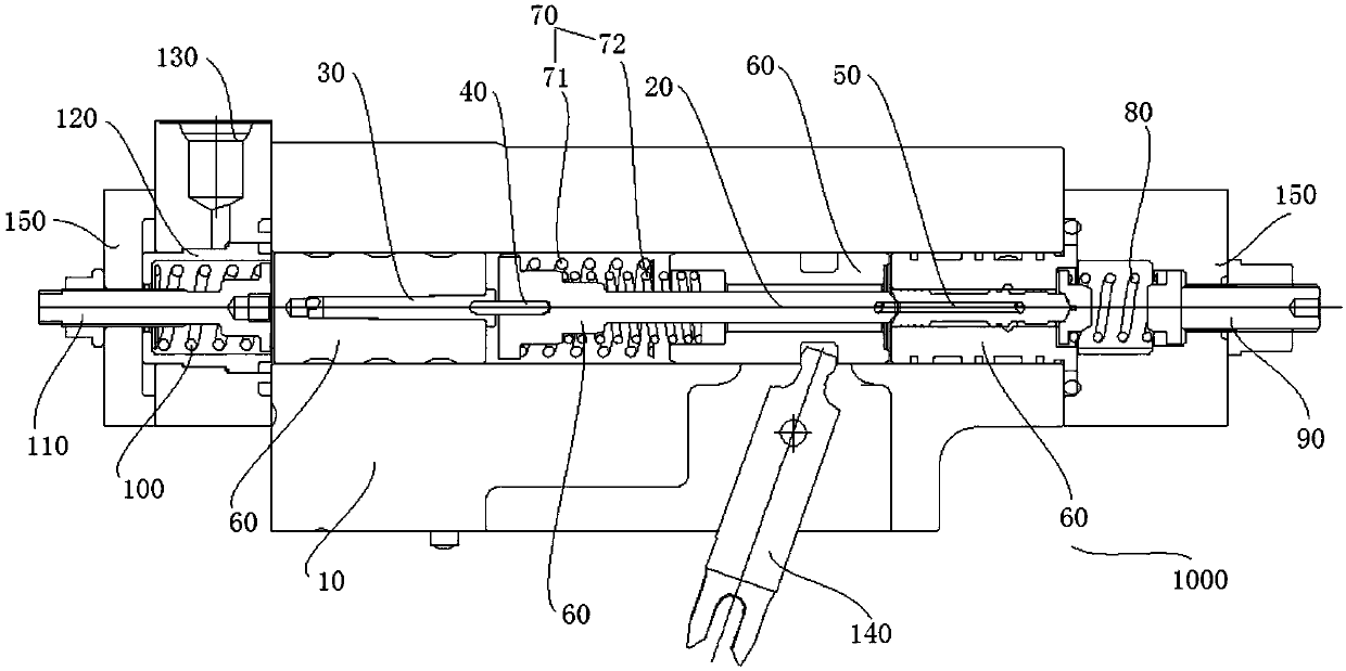
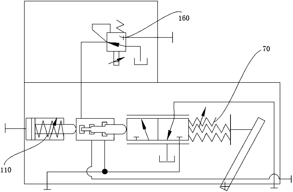
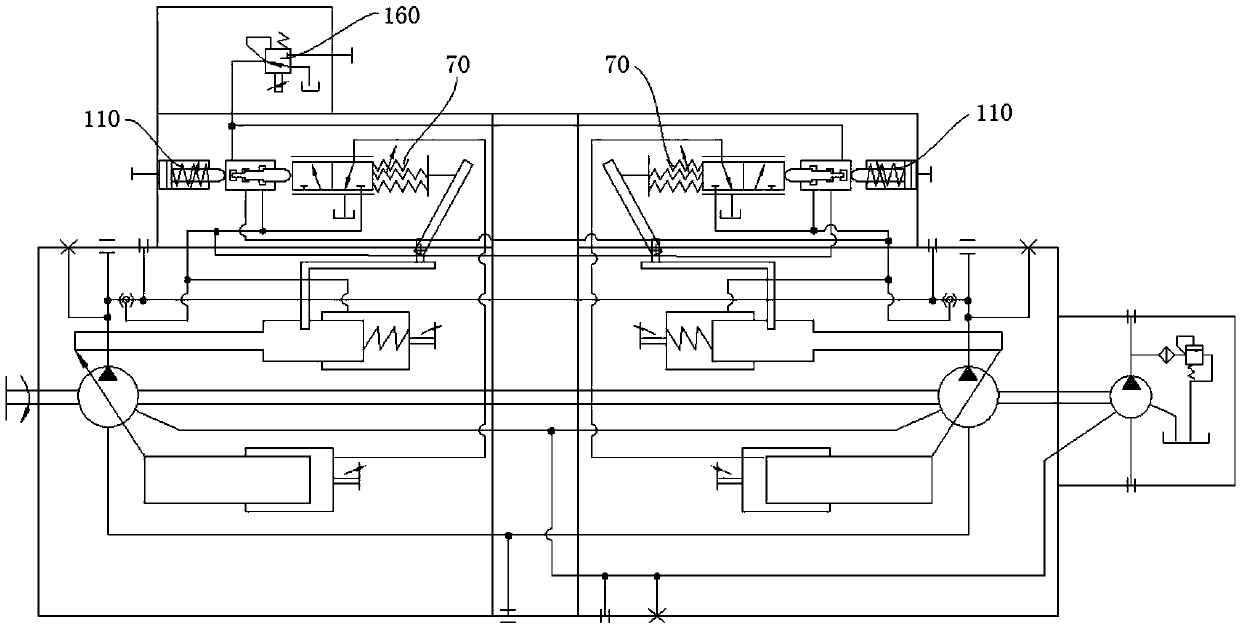
[0053] Such as Figure 1 to Figure 3 As shown, the hydraulic pump control valve 1000 according to the embodiment of the present invention includes a main valve body 10...


PUM


Abstract

The invention provides a hydraulic pump control valve which comprises a main valve body, a first guide bar, a power control piloted valve element, a second guide bar, a valve element, a plurality of valve sleeves, a power control piece, a power adjusting piece, a negative flow control piece and a negative flow adjusting piece; the plurality of valve sleeves separately sleeve on the outer wall surfaces of the first guide bar, the power control piloted valve element, the second guide bar and the valve element and are separated from the outer wall surfaces of the first guide bar, the power control piloted valve element, the second guide bar and the valve element to define a gap, and the first guide bar, the power control piloted valve element, the second guide bar and the valve element can move in the gap separately; the power control piece is arranged on the end surface of at least one valve sleeve to control the output power of the hydraulic pump; the power adjusting piece is arranged at one end of the main valve body and at least one part of the power adjusting piece leans against a mounting hole; and the negative flow adjusting piece is arranged at the other end of the main valve.According to the hydraulic pump control valve provided by the invention, the flow change of oil liquor output by the hydraulic pump and power change of the hydraulic pump can be controlled and adjusted effectively.

Description

Technical field [0001] The present invention relates to the technical field of hydraulic pump manufacturing, and more specifically, to a hydraulic pump control valve. Background technique [0002] The hydraulic pump control valve is a component used to control oil pressure, flow and direction. When the existing hydraulic pump control valve is working, the guide rod between the push rod of the electromagnet and the spool of the control valve is prone to jamming, which increases frictional resistance and causes the control valve to have hysteresis characteristics. In addition, the existing hydraulic pump control valve has a complex structure, many parts and high processing costs. Summary of the invention [0003] In view of this, the present invention provides a hydraulic pump control valve. [0004] To solve the above technical problems, the present invention adopts the following technical solutions: [0005] The hydraulic pump control valve according to the embodiment of the presen...

Claims


Application Information

Patent Timeline
Patent Type & Authority Applications(China)
IPC IPC(8): F04B1/26F15B13/02
CPCF04B1/26F04B49/002F15B13/02
Inventor 汪立平张振寿李童
Owner JIANGSU HENGLI HYDRAULIC TECH CO LTD
Features
  • R&D
  • Intellectual Property
  • Life Sciences
  • Materials
  • Tech Scout
  • Unparalleled Data Quality
  • Higher Quality Content
  • 60% Fewer Hallucinations
Learn More