Air compression buffering device

A buffer device and air compression technology, which is applied in reducing greenhouse gases, climate sustainability, hydroelectric power generation, etc., and can solve problems such as oil pollution, stuck on the piston, and water entering the valve port

Active Publication Date: 2012-09-19
HARBIN XUNPU TECH DEV
View PDF8 Cites 4 Cited by
  • Summary
  • Abstract
  • Description
  • Claims
  • Application Information

AI Technical Summary

Problems solved by technology

When the air is added, the vacuum disappears immediately, and the valve cover returns to close quickly under the action of the main spring. During the closing process, the contact surface between the valve cover and the valve seat produces a huge impact, not only the working noise is large, but also the valve is often broken. Shaft, leading to accident of flooded unit
For this reason, buffer devices are added to the air supply valve, such as oil buffer, air damping buffer, and multiple shut-off valve air compression buffer devices on the circumference of the piston. These buffer devices have certain defects in the actual operation of the air supply valve. For example, the oil buffer device is a two-way damping buffer, not only cannot make the air supply valve meet the technical requirements of quick opening, quick return, and slow closing when in place, but also the buffer medium oil often leaks under the damping pressure, causing problems of buffer failure and oil pollution; The air damping buffer device that adjusts the buffer plug to adjust the intake and exhaust air cannot solve the air supply volume and the opening and closing time of the air supply valve cover required by the random vacuum degree generated by the turbine or other equipment. The vacuum degree formed each time is random, so it is required The performance of the buffer device must meet its randomness; some buffer devices are equipped with 2 to 4 stop valves on the buffer piston. It rotates at high speed, so the cut-off valve installed on the buffer piston is often stuck on the piston during the movement, causing the valve cover to fail to close, resulting in serious accidents of water entering the valve port. The hydro generator urgently needs a buffer device that can overcome the above-mentioned buffer device. Defects, safe and reliable new buffer device that meets the working conditions of the air supply valve

Method used


Image

  • Air compression buffering device
  • Air compression buffering device
  • Air compression buffering device

Examples


Embodiment Construction

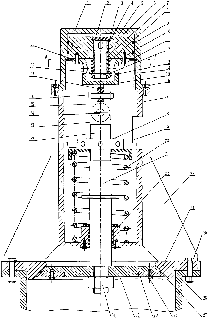
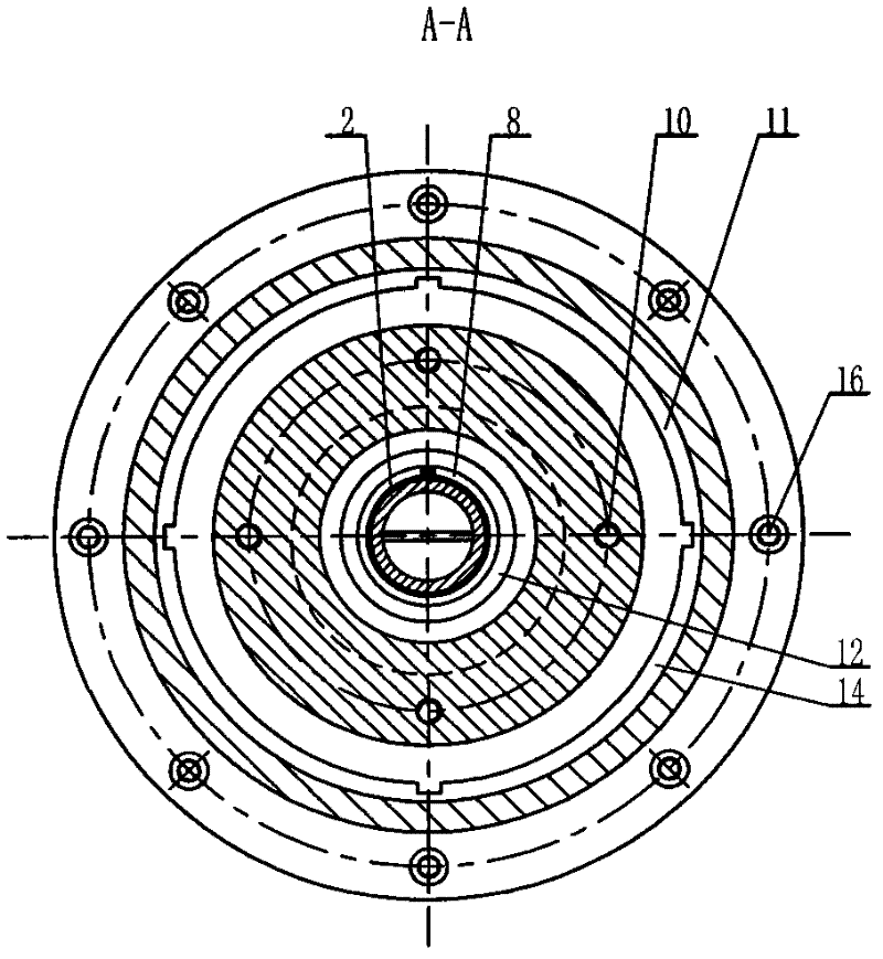
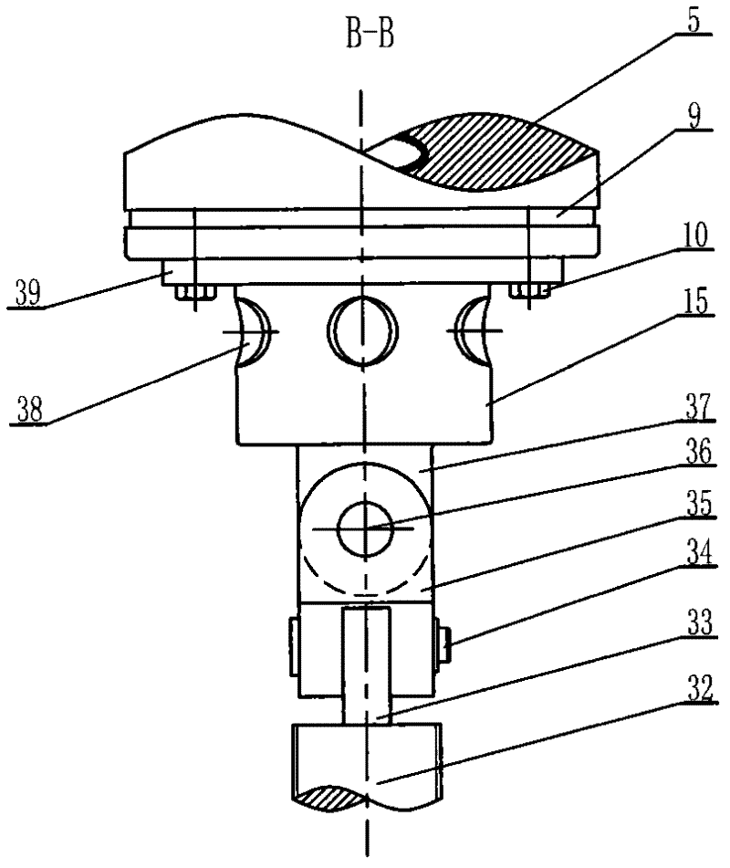
[0012] Put the stop valve O-ring (3) on the upper end of the reverse cut-off hollow valve (2) with 2 to 4 upper air inlet holes (4) and the air inlet pipe (6), and then put the reverse cut-off hollow valve (2 ) into the central guide hole (7) of the buffer piston (5), and can slide up and down freely. Put the cut-off valve spring (8) on the lower end of the reverse cut-off hollow valve (2), then install the retaining ring (12) on the lower end of the stop valve spring (8), and reverse the cut-off hollow valve ( 2) Fix the upper stop ring stop pin (13). Have 2~4 side air intake holes (38) on the outer surface of hole type fixed head (15), there is fixed head to connect orifice plate (37) below hole type fixed head (15), fix bolt (10) with piston The hole type fixed head (15) is fixed on the lower end of the buffer piston (5) through the connecting flange (39), and two oil storage ring grooves (9) are opened on the outer surface of the buffer piston (5). Connect the fixed head...


PUM


Abstract

The invention discloses an air compression buffering device. The key technical scheme of the invention is as follows: a reverse cut-off hollow core valve with 2-4 upper air inlets and an air intake pipe is arranged inside a central guide hole of a buffering piston; and a stop valve spring, a baffle ring and a baffle ring stop pin are arranged at the lower end of the reverse cut-off hollow core valve. The lateral side of a hole-type fixing head is provided with 2-4 lateral air inlets; and the hole-type fixing head is fixed together with the buffering piston and the hole-type fixing head is connected together with a valve shaft through a cross connector. An annular empty groove and 2-4 axial exhaust grooves are machined on the internal surface of the bottom surface of a buffering cylinder, and after sleeved on the buffering piston, the buffering cylinder is fixed on a main spring protecting tube through a mesoposition hexagon socket bolt. The air compression buffering device can be extensively applied to rotation gulp valves and static gulp valves.

Description

Technical field: [0001] The invention relates to an air compression buffer device for operating an air supplement valve. Background technique: [0002] When the hydro-generator set is operated out of the rated working condition, a momentary vacuum will be generated under the hydro-turbine, which will cause vibration and lifting of the hydro-turbine during operation, resulting in damage to the unit, and will also aggravate the degree of cavitation of the hydro-turbine. For this reason, a running air supply valve is installed on the upper end of the main shaft of the turbine. When the instantaneous vacuum generated by the turbine is greater than the specified limit value, the running air supply valve will overcome the elastic force of the main spring, open the valve cover, and fill the vacuum area of ​​the turbine. Air, eliminate unit vibration, avoid lifting the machine, and reduce the degree of cavitation. When the air is added, the vacuum disappears immediately, and the va...

Claims


Application Information

Patent Timeline
Patent Type & Authority Applications(China)
IPC IPC(8): F03B11/04
CPCY02E10/226Y02E10/20
Inventor 韩宏波
Owner HARBIN XUNPU TECH DEV
Why Eureka
Try Eureka