
Method for manufacturing fuse trimming chip

A manufacturing method and trimming technology, applied in semiconductor/solid-state device manufacturing, electrical components, circuits, etc., can solve problems such as product yield decline, and achieve the effect of improving reliability

Active Publication Date: 2018-03-09
CSMC TECH FAB2 CO LTD
View PDF5 Cites 5 Cited by
  • Summary
  • Abstract
  • Description
  • Claims
  • Application Information

AI Technical Summary

Problems solved by technology

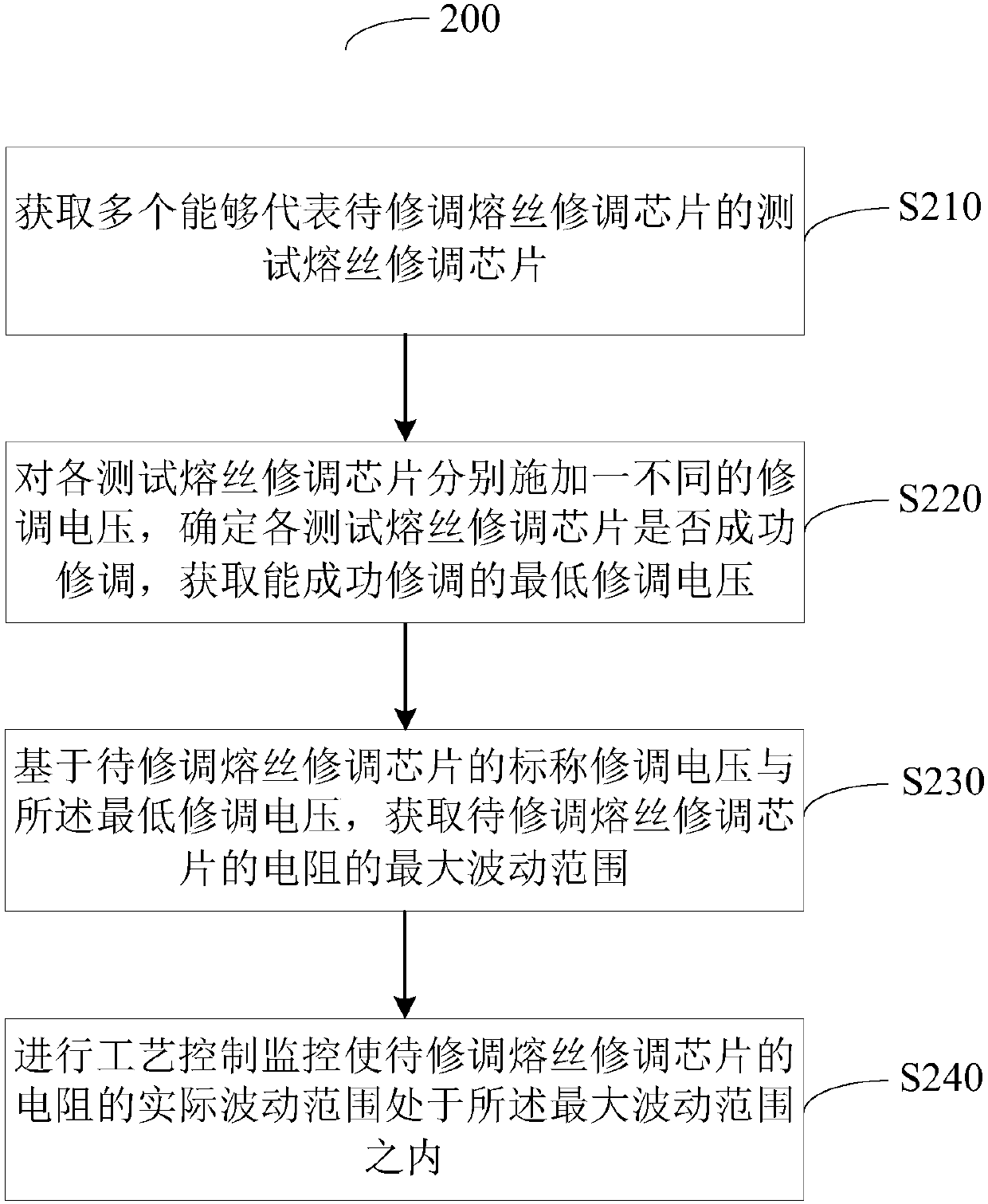
[0004] In order to improve the problem of product yield decline caused by unsuccessful trimming in the prior art and improve the reliability of fuse trimming, the present invention provides a method for manufacturing a fuse trimming chip. The method includes: obtaining multiple A test fuse trimming chip that can represent the fuse trimming chip to be trimmed; apply a different trimming voltage to each test fuse trimming chip, determine whether each test fuse trimming chip is successfully trimmed, and obtain The lowest trimming voltage that can be successfully trimmed; based on the nominal trimming voltage of the fuse trimming chip to be trimmed and the minimum trimming voltage, obtain the maximum fluctuation range of the resistance of the fuse trimming chip to be trimmed ; Carry out process control monitoring (PCM) to make the actual fluctuation range of the resistance of the fuse trimming chip to be repaired within the maximum fluctuation range

Method used

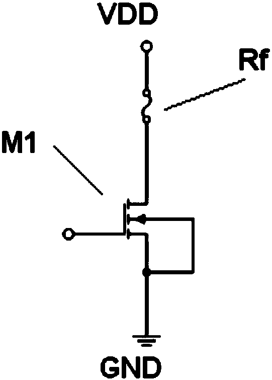
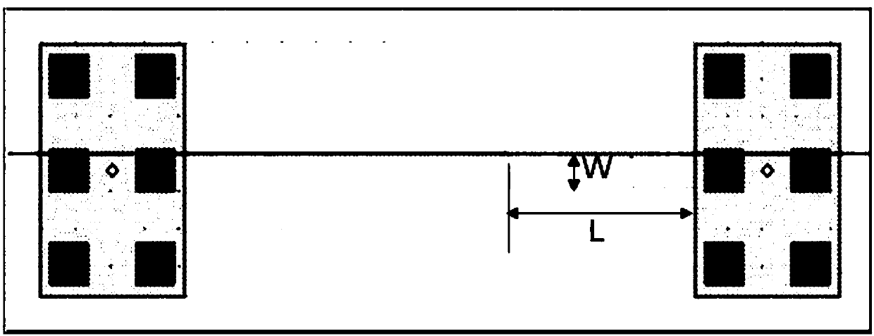

Image

  • Method for manufacturing fuse trimming chip
  • Method for manufacturing fuse trimming chip
  • Method for manufacturing fuse trimming chip

Examples


Embodiment Construction

[0021] In the following description, numerous specific details are given in order to provide a more thorough understanding of the present invention. It will be apparent, however, to one skilled in the art that the present invention may be practiced without one or more of these details. In other examples, some technical features known in the art are not described in order to avoid confusion with the present invention.

[0022] It should be understood that the invention can be embodied in different forms and should not be construed as limited to the embodiments set forth herein. Rather, these embodiments are provided so that this disclosure will be thorough and complete, and will fully convey the scope of the invention to those skilled in the art.

[0023] The terminology used herein is for the purpose of describing particular embodiments only and is not intended to be limiting of the invention. As used herein, the singular forms "a", "an" and "the / the" are intended to include...


PUM


Abstract

The invention provides a method for manufacturing a fuse trimming chip. The method comprises the steps of: acquiring a plurality of test fuse trimming chips capable of representing a fuse trimming chip to be trimmed; applying a different trimming voltage to each test fuse trimming chip, determining whether each test fuse trimming chip is successfully trimmed, and acquiring the lowest trimming voltage for successful trimming; based on the nominal trimming voltage of the fuse trimming chip to be trimmed and the lowest trimming voltage, acquiring the maximum fluctuation range of the resistance ofthe fuse trimming chip to be trimmed; and performing process control monitoring so that the actual fluctuation range of the resistance of the fuse trimming chip to be trimmed is within the maximum fluctuation range. The method can calculate the maximum fluctuation range allowed by the resistance of the fuse trimming chip to be trimmed with process fluctuation, so that the actual fluctuation rangeof the resistance of the fuse trimming chip to be trimmed can be within the maximum allowable fluctuation range through process control monitoring, and the fuse trimming reliability is improved.

Description

technical field [0001] The invention relates to the technical field of semiconductors, in particular to a method for manufacturing a fuse trimming chip. Background technique [0002] With the development and progress of technology, more and more chips will use the method of post-package trimming for circuit design. The advantage of this design is that it can avoid package drift, simplify mid-test items, and reduce mid-test costs. It is more suitable for Some high-precision and packaged chips need to be programmed. [0003] The polysilicon fuse adjustment chip (Poly fuse) is an excellent low-density solution, which has the characteristics of high reliability and small size, and is widely used in various process platforms. In order to improve the success rate of trimming, the polysilicon fuse trimming chip chooses a polycrystalline resistor with a small width and length, such as the smallest metal cobalt silicide polycrystalline resistor. Taking the 0.18 micron (um) process a...

Claims


Application Information

Patent Timeline
Patent Type & Authority Applications(China)
IPC IPC(8): H01L21/768H01L21/66
CPCH01L21/768H01L22/14
Inventor 张楠高瞻周晶王浩温多武范蓉孙贵鹏郭术明张威彦肖金玉杨晓寒李达
Owner CSMC TECH FAB2 CO LTD
Learn More