Laser encapsulation method

A laser packaging and laser beam technology, applied in semiconductor devices, electrical components, circuits, etc., to achieve the effect of excellent yield, excellent overall quality and good adaptability

Active Publication Date: 2020-01-24
SHANGHAI MICRO ELECTRONICS EQUIP (GRP) CO LTD
View PDF7 Cites 0 Cited by
  • Summary
  • Abstract
  • Description
  • Claims
  • Application Information

AI Technical Summary

Problems solved by technology

[0005] The invention provides a laser encapsulation method to solve the problem that the glass frit forms dense holes inside and near the edge

Method used


Image

  • Laser encapsulation method
  • Laser encapsulation method
  • Laser encapsulation method

Examples


Embodiment 1

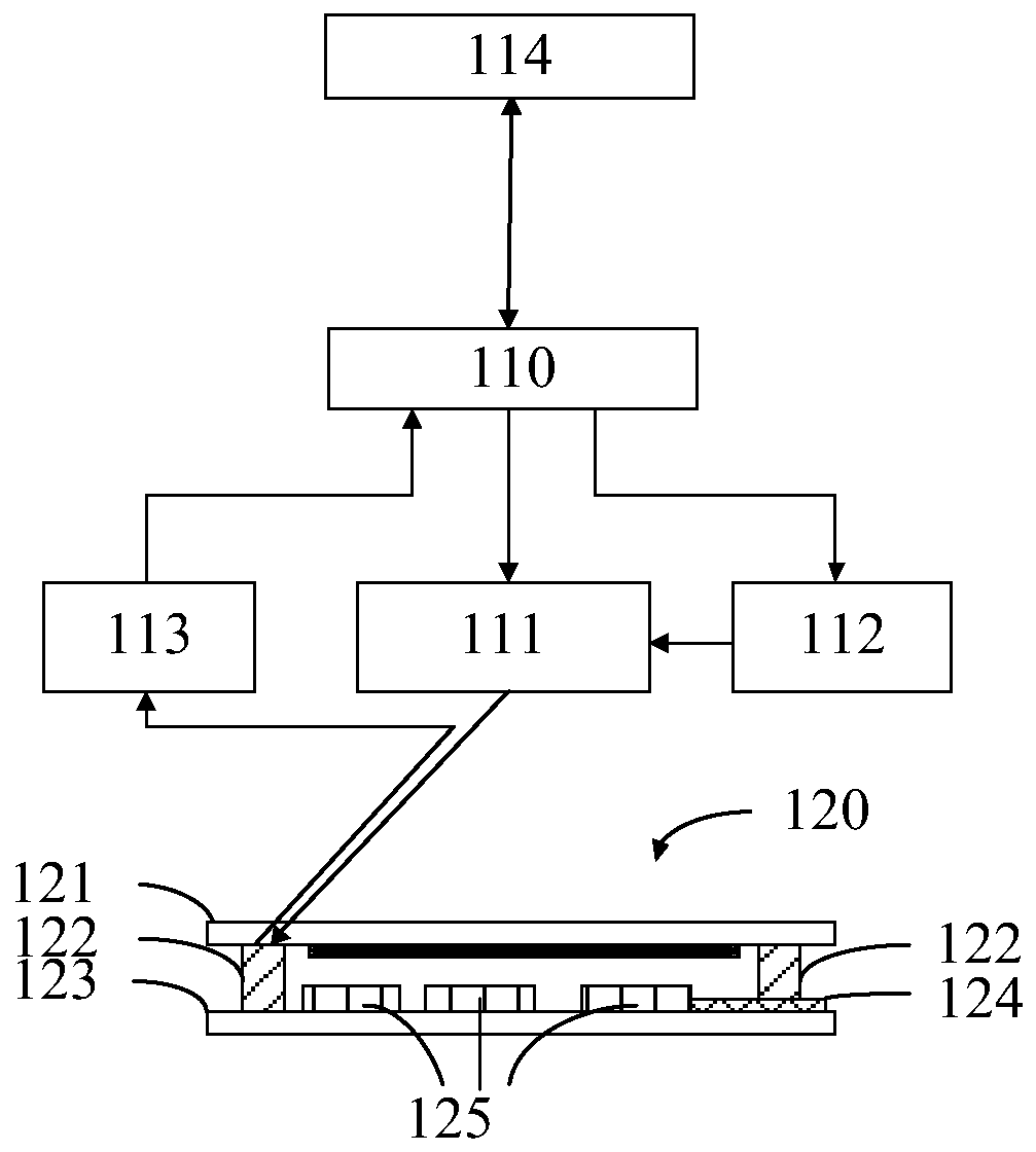
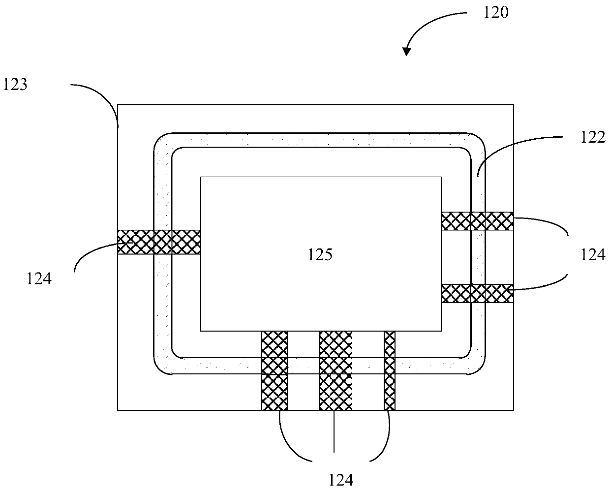
[0050] This embodiment is used to form an airtight seal on the OLED display 120 using glass frit, wherein the OLED display 120 is a typical glass package, and the main structure of the OLED display 120 includes a cover glass 121, a glass frit 122, and a substrate glass 123 , OLED layer 125 and electrode 124 . Wherein, the glass frit 122 is located on the substrate glass 123 of the OLED display 120, and its top view is shown as Figure 1b shown. The glass frit 122 is pre-cured on the substrate glass 123 through screen printing and pre-sintering steps to form a rounded rectangular sealing line with a certain thickness. The OLED layer 125 on the substrate glass 123 is located inside the sealing line of the glass frit 122 , and there are electrodes 124 on the substrate glass 123 connecting the inside and outside of the OLED display 120 .

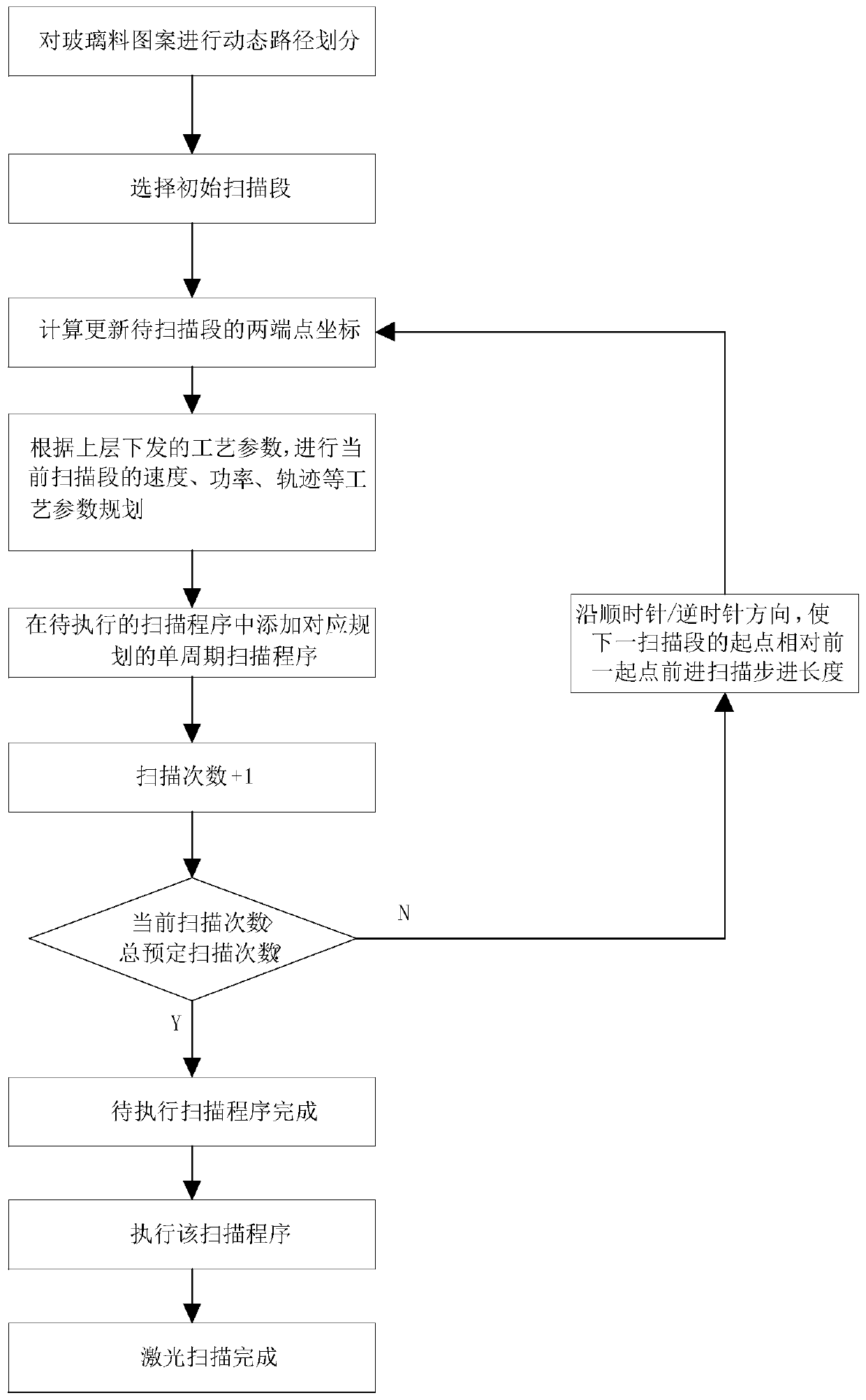
[0051] Such as figure 2 As shown, the present invention provides a laser packaging method, using a laser to heat the glass frit 122 pattern...

Embodiment 2

[0076] The difference between this embodiment and Embodiment 1 is that the pattern of the glass frit 122 is a non-sealed pattern, including straight lines and open lines of any shape.

[0077] Therefore, if Figure 12 to Figure 15 As shown, step 1 of this embodiment includes:

[0078] The frit 132 pattern is divided into N counterclockwise or clockwise 1 scan segments, from the first scan segment to the Nth scan segment 1 -The positions between the start point 133 and the start point 133, the end point 134 and the end point 134 of two adjacent scan segments 132 in one scan segment 132 are offset by L 1 , L 1 much less than the length L of the first scanning segment 132 3 ;

[0079] If take N 1 =Ceiling(L / L 1 )-(L 3 / L 1 )+1, the Nth 1 - 1 scan segment 132 with Nth 1 Position offset L between the starting point 133 and the starting point 133 of each scanning segment 132 1 , the position offset L between the end point 134 and the end point 134 2 , where L is the tot...

Embodiment 3

[0090] Such as Figure 16-17 As shown, the difference between this embodiment and Embodiment 1 and Embodiment 2 is that in this embodiment, the glass frit 122 pattern can be divided into a plurality of sub-scanning areas 210, and adjacent sub-scanning areas 210 have overlapping areas 211, so The length of the overlapping region 211 is usually the length of one scanning segment. Generally, the length of the sub-scanning area 210 should be much longer than the length of the scanning segment. For a single sub-scanning area 210, its path planning and scanning steps are the same as those in Embodiment 1 or Embodiment 2, and will not be repeated here. The package scanning order for the plurality of sub-scanning areas 210 can be arbitrary. The single sub-scanning area 210 has the following characteristics after completing the dynamic quasi-synchronous scanning:

[0091] The areas at both ends of the sub-scanning area 210 are defined as overlapping areas 211 , and the areas between...


PUM

PropertyMeasurementUnit
lengthaaaaaaaaaa

Abstract

The invention discloses a laser packaging method, comprising: step 1: performing path planning on a glass frit pattern, thereby dividing the glass frit pattern into several scanning sections, and the same-side endpoints of two adjacent scanning sections are aligned in the same direction There is a position offset, and there is an overlap between two adjacent scan segments, wherein the offset of the position offset is much smaller than the length of any scan segment in the plurality of scan segments; Step 2: use the laser beam to The scanning segments are scanned one by one until all the frit patterns are scanned. The invention provides quasi-synchronous uniform heating locally, so that the glass frit can reach a molten state in a short period of time, and also produces a scanning effect similar to a circle on a macroscopic level, so that the entire glass frit is softened and packaged successively, and a healthy The glass wall with controllable ratio and good packaging quality has a very small number of tiny holes on both sides of the glass frit; the density of the material is consistent with the perimeter, the size of the holes is slightly larger than the perimeter, no cracks, and the overall quality is excellent.

Description

technical field [0001] The invention relates to the field of laser packaging, in particular to a laser packaging method. Background technique [0002] Optoelectronic semiconductor devices have been widely used in various fields of life. Among them, OLED (Organic Light Emitting Diode) has become a research hotspot due to its good color ratio, wide viewing angle, and high response speed, and has a good application prospect. However, the electrodes and organic layers in OLED displays are very sensitive to oxygen and moisture. Oxygen and moisture permeating into the OLED device from the external environment will seriously shorten the life of the OLED device. Therefore, it is very important to provide an effective hermetic seal for OLED devices. [0003] In recent years, a sealing method using frit-assisted laser heating has been applied to the sealing of OLED displays. The glass frit is doped with a material having a high absorption rate for a specific light wavelength and h...

Claims


Application Information

Patent Timeline
Patent Type & Authority Patents(China)
IPC IPC(8): H01L51/52H01L21/67
CPCH01L21/67115H01L21/67126H10K50/8426
Inventor 黄元昊
Owner SHANGHAI MICRO ELECTRONICS EQUIP (GRP) CO LTD
Why Eureka
Try Eureka