Flatness calibration method and system
A calibration method and flatness technology, applied in the field of flatness calibration methods and systems, can solve the problems of high operating load, large workload, poor flexibility, etc.
- Summary
- Abstract
- Description
- Claims
- Application Information
AI Technical Summary
Problems solved by technology
Method used
Image
Examples
Embodiment 1
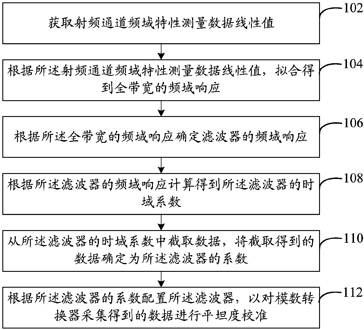
[0031] refer to figure 1 , shows a flowchart of steps of a flatness calibration method in Embodiment 1 of the present invention. In this embodiment, the flatness calibration method includes:
[0032] Step 102, acquiring the linear value of the frequency domain characteristic measurement data of the radio frequency channel.
[0033] In this embodiment, the received power of the radio frequency channel may be normalized to obtain the linear value of the frequency domain characteristic measurement data of the radio frequency channel. Wherein, normalization processing may be performed with a determined central frequency point, but not limited thereto.
[0034] Step 104, according to the linear value of the measurement data of the frequency domain characteristic of the radio frequency channel, the frequency domain response of the full bandwidth is obtained by fitting.
[0035] In this embodiment, the frequency domain response of the entire bandwidth may be obtained by linear fit...
Embodiment 2
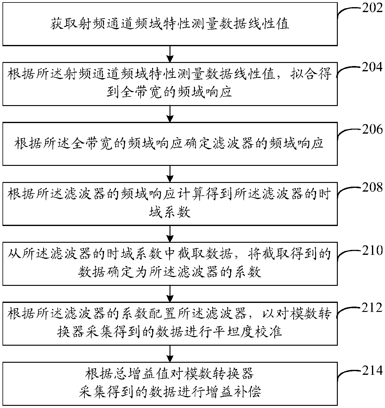
[0047] refer to figure 2 , shows a flowchart of steps of a flatness calibration method in Embodiment 2 of the present invention. In this embodiment, the flatness calibration method includes:
[0048] Step 202, acquiring the linear value of the frequency domain characteristic measurement data of the radio frequency channel.
[0049] In this embodiment, local oscillators may be fixed according to the actual bandwidth of the receiving channel, and the number of local oscillators and the number of gains for each local oscillator may be determined. When obtaining the linear value of the measurement data of the frequency domain characteristics of the radio frequency channel, multiple point data on the frequency domain of the radio frequency channel can be obtained according to the number of local oscillators, the number of gains and the number of measurement points under each gain; then, according to the The point data determines the linear value of the frequency domain character...
Embodiment 3
[0062] In combination with the foregoing embodiments, this embodiment takes the flatness calibration of the intermediate frequency band as an example to describe the flatness calibration method in detail. In this embodiment, the specific flow of the flatness calibration method can be as follows:
[0063] S31. Obtain a linear value of the frequency domain characteristic measurement data of the radio frequency channel.
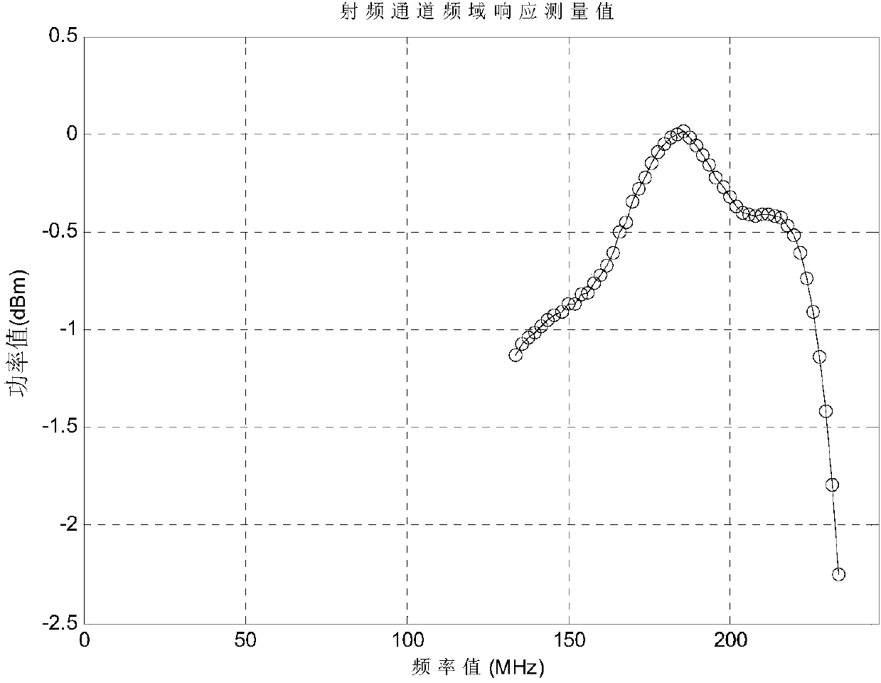
[0064] In this embodiment, assuming that the design bandwidth of the receiving channel of the comprehensive testing instrument is 100 MHz, the local oscillator can be fixed first, and the flatness within the 100 MHz bandwidth can be tested to obtain a curve. Specifically, the comprehensive tester currently has 53 local oscillators. Considering that the flatness of different gains is also different, the current number of gains is 82. If all of them are tested, the test period will be longer. In order to save time, in this embodiment , Divide 82 gains into 11 gro...
PUM
 Abstract
Description
Claims
Application Information
 - R&D
- Intellectual Property
- Life Sciences
- Materials
- Tech Scout
- Unparalleled Data Quality
- Higher Quality Content
- 60% Fewer Hallucinations
Browse by: Latest US Patents, China's latest patents, Technical Efficacy Thesaurus, Application Domain, Technology Topic, Popular Technical Reports.
© 2025 PatSnap. All rights reserved.Legal|Privacy policy|Modern Slavery Act Transparency Statement|Sitemap|About US| Contact US: help@patsnap.com


