Closed scanning galvanometer device for laser machine

A scanning galvanometer and closed technology, which is applied in the field of closed scanning galvanometer devices, can solve the problems of unstable relative position and easy to be interfered by dust in the air, and achieve the effect of compact structure, small influence and precise optical path control

Pending Publication Date: 2018-03-13
广东铭钰科技股份有限公司
View PDF0 Cites 3 Cited by
  • Summary
  • Abstract
  • Description
  • Claims
  • Application Information

AI Technical Summary

Problems solved by technology

The disadvantage of this method is that the laser light path moves in an open space, which is easily disturbed by dust in the air, and the field lens is fixed on the casing alone, and its relative position relative to the Y galvanometer and X galvanometer is unstable. It is necessary to reserve a larger range for the field lens

Method used


Image

  • Closed scanning galvanometer device for laser machine
  • Closed scanning galvanometer device for laser machine
  • Closed scanning galvanometer device for laser machine

Examples


Embodiment 1

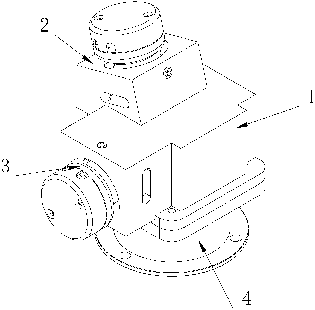
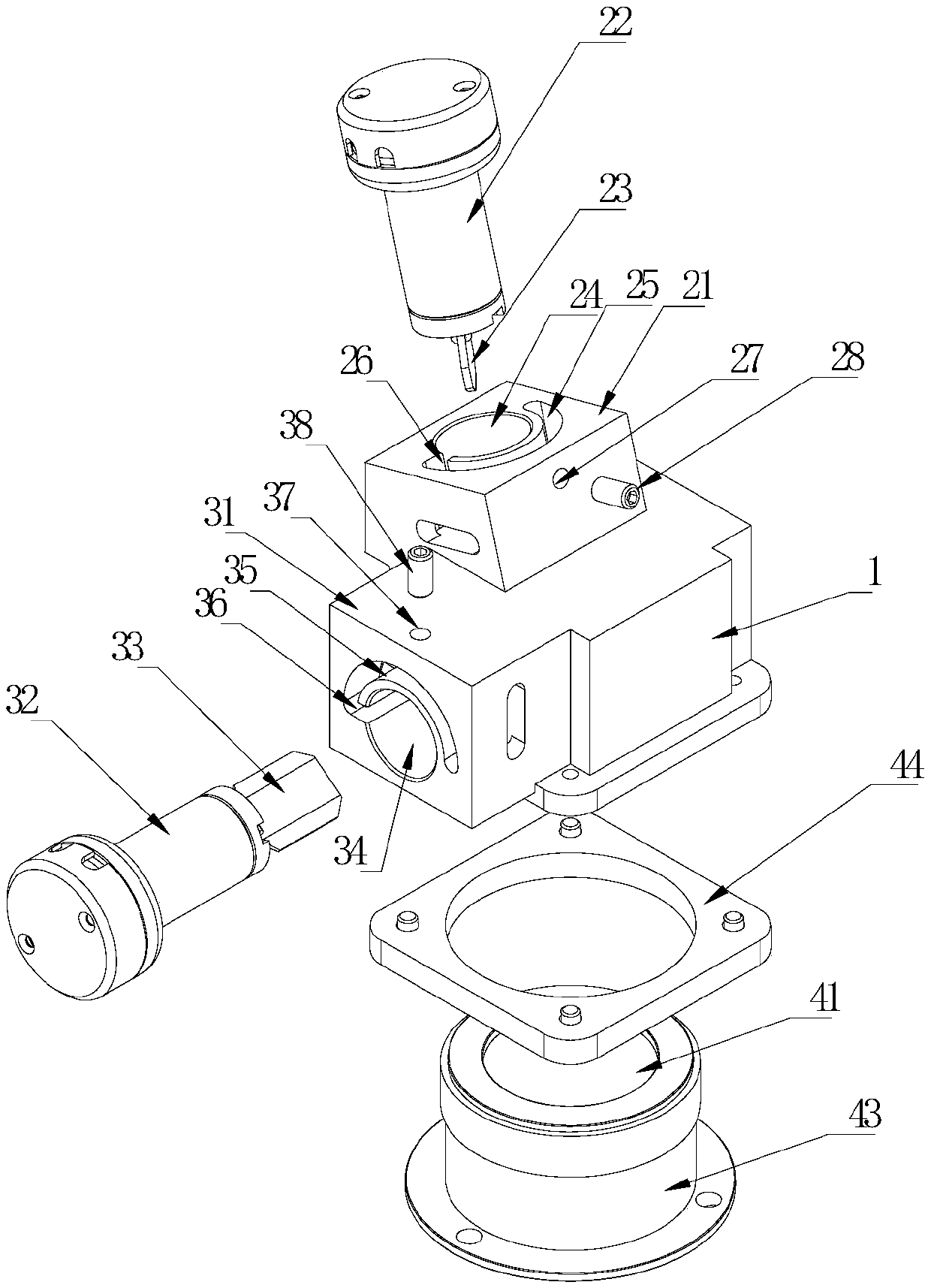
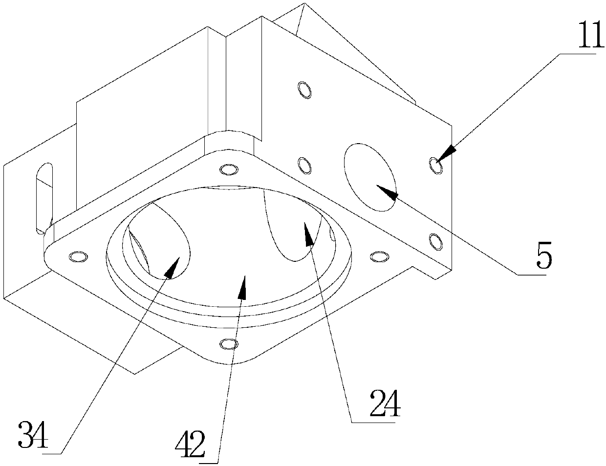
[0038] This embodiment provides a kind of airtight scanning galvanometer device for laser machine, such as figure 1 -3, it should be noted that the "front" and "rear" in this embodiment both refer to the propagation of the laser light from front to back. The sealed scanning vibrating mirror device includes: base 1, X vibrating mirror mechanism 2, Y vibrating mirror mechanism 3, field mirror mechanism 4;

[0039] The X vibrating mirror mechanism 2 includes an X vibrating mirror motor 22, an X vibrating mirror lens 23 driven by the X vibrating mirror motor 22, and an X vibrating mirror seat 21. The X vibrating mirror seat 21 is provided with an X retainer for fixing the X vibrating mirror motor 22. Hole 24.

[0040] The X vibration lens 23 is fixedly connected to the output shaft of the X vibration mirror motor 22, and the X vibration mirror motor 22 drives the X vibration lens 23 to swing.

[0041] The Y vibrating mirror mechanism 3 includes a Y vibrating mirror motor 32, a Y...


PUM


Abstract

The invention provides a closed scanning galvanometer device for a laser machine. The device comprises a base, an X galvanometer mechanism, a Y galvanometer mechanism and a field lens mechanism. The Xgalvanometer mechanism comprises an X galvanometer motor, an X galvanometer lens and an X galvanometer base which is provided with an X positioning hole, the Y galvanometer mechanism comprises a Y galvanometer motor, a Y galvanometer lens and a Y galvanometer base which is provided with a Y positioning hole, the field lens mechanism comprises a field lens, the front end of the base is provided with a laser incidence hole, the bottom of the base is provided with a field lens installation hole, the field lens is installed in the field lens installation hole, the X positioning hole, the Y positioning hole, the field lens installation hole and the laser incidence hole are mutually connected in a cavity, and the cavity is provided with no other through hole except for the X positioning hole, the Y positioning hole, the field lens installation hole and the laser incidence hole. The scanning galvanometer device fixes the Y galvanometer motor, the X galvanometer motor and the field lens, therelative positions are more stable, the closed cavity is formed in the base after fixing, and dust pollution is small when a laser beam passes.

Description

technical field [0001] The invention relates to a sealed scanning vibrating mirror device for a laser machine. Background technique [0002] The basic principle of laser marking is that a high-energy continuous laser beam is generated by a laser generator, and the focused laser acts on the printing material to instantly melt or even gasify the surface material. By controlling the path of the laser on the surface of the material, a Graphical markup required. [0003] Laser marking is characterized by non-contact processing, which can be marked on any special-shaped surface without deformation and internal stress on the workpiece. It is suitable for marking metal, plastic, glass, ceramics, wood, leather and other materials. [0004] Lasers can mark almost all parts (such as pistons, piston rings, valves, valve seats, hardware tools, sanitary ware, electronic components, etc.), and the marks are wear-resistant, the production process is easy to automate, and the deformation of...

Claims


Application Information

Patent Timeline
Patent Type & Authority Applications(China)
IPC IPC(8): B23K26/362B23K26/70G02B26/10
CPCB23K26/361B23K26/702G02B26/101
Inventor 利晓宏
Owner 广东铭钰科技股份有限公司
Why Eureka
Try Eureka