Self-removing robot

A self-moving and robotic technology, applied in the direction of manipulators, motor vehicles, manufacturing tools, etc., can solve problems such as unstable operation, failure to pass obstacles smoothly, and dead spots in the obstacle crossing angle, and achieve a compact and reasonable structure.

Pending Publication Date: 2018-03-13
ECOVACS ROBOTICS (SUZHOU ) CO LTD
View PDF9 Cites 4 Cited by
  • Summary
  • Abstract
  • Description
  • Claims
  • Application Information

AI Technical Summary

Problems solved by technology

The above-mentioned prior art has the following deficiencies: 1. It is impossible to pass all obstacles smoothly, and there is a dead point in the obstacle-crossing angle; 2. The auxiliary driving force has pulse fluctuations, and the operation is not stable; 3. The auxiliary driving force provided is insufficient
The above prior art also has the following deficiencies: 1. The mechanism takes up a lot of space and cannot be generally applied to most self-propelled robots, especially for self-propelled robots, if this mechanism is adopted, the water tank cannot be installed; 2. One more driving wheel is provided motor, the power consumption is greatly increased

Method used

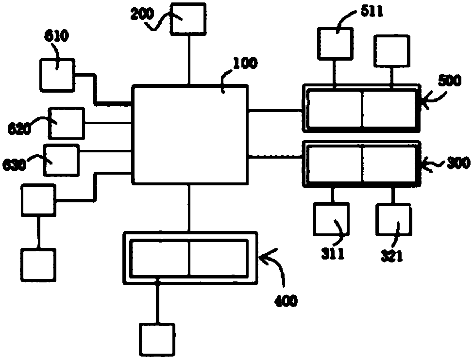

Image

  • Self-removing robot
  • Self-removing robot
  • Self-removing robot

Examples


Embodiment 2

[0040] It can be known from the above that the self-propelled robot provided by the present invention triggers and activates the secondary drive wheel assembly through contact between the trigger end and an obstacle, which belongs to mechanical triggering. For those skilled in the art, it is also possible to realize the assisted obstacle surmounting of the self-mobile robot through other alternative mechanisms.

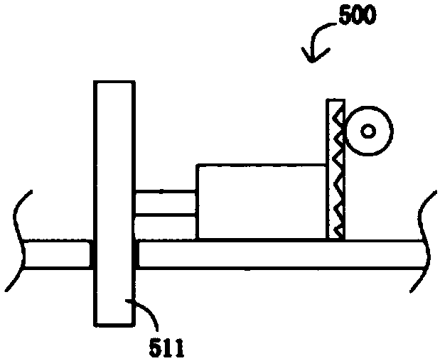
[0041] Figure 7 It is a schematic diagram of a partial structure of a gear transmission assembly in Embodiment 2 of the present invention. Such as Figure 7 As shown, the connecting rod assembly of the self-mobile robot can be slidably arranged on the body 1000 or the main driving wheel assembly 200, and a gear transmission assembly 600 is provided between the trigger mechanism and the connecting rod assembly; The end is lifted up after encountering an obstacle, so that the gear transmission assembly rotates and drives the connecting rod assembly to slide downward,...

Embodiment 3

[0044] Figure 8 It is a schematic diagram of a partial structure of a hydraulic transmission assembly in Embodiment 3 of the present invention. Such as Figure 8 As shown, the connecting rod assembly of the self-mobile robot can be slidably arranged on the body 1000 or the main driving wheel assembly 200, and a hydraulic transmission assembly 700 is provided between the trigger mechanism and the connecting rod assembly; The end is lifted up after encountering an obstacle, pressing the hydraulic transmission assembly, so that the connecting rod assembly slides downward under the pressure of the hydraulic transmission assembly, and the auxiliary driving wheel descends relative to the main body or the main driving wheel assembly contact with the walking surface A.

[0045] Other technical features in this embodiment are the same as those in Embodiment 1. Please refer to the content of Embodiment 1 above, and details will not be repeated here.

[0046] In addition, in addition...


PUM


Abstract

The invention discloses a self-removing robot. The self-removing robot comprises a moving robot body (1000) as well as a control unit and a primary drive wheel assembly (200) which are arranged on theself-removing robot body (1000), and further comprises a secondary drive wheel assembly (300) and a trigger mechanism connected with the secondary drive wheel assembly, wherein the primary drive wheel assembly comprises a drive motor (100) and a drive wheel (201); the secondary drive wheel assembly comprises a connecting rod assembly (400) and a secondary drive wheel (301) arranged at one end ofthe connecting rod assembly; the connecting rod assembly can be movably arranged on the body or the primary drive wheel assembly; the trigger mechanism at least comprises a trigger end (401); in a forward direction, the trigger end is positioned before the primary drive wheel; after the trigger end encounters an obstacle and is lifted, downward acting force is generated on the secondary drive wheel, and the secondary drive wheel performs descending motion relative to the body under downward acting force or increases positive pressure on the travelling surface. The self-removing robot effectively avoids a dead point phenomenon, is adjustable in height, is suitable for obstacle crossing requirements of various complicated terrains, is compact in structure, and is reasonable in layout.

Description

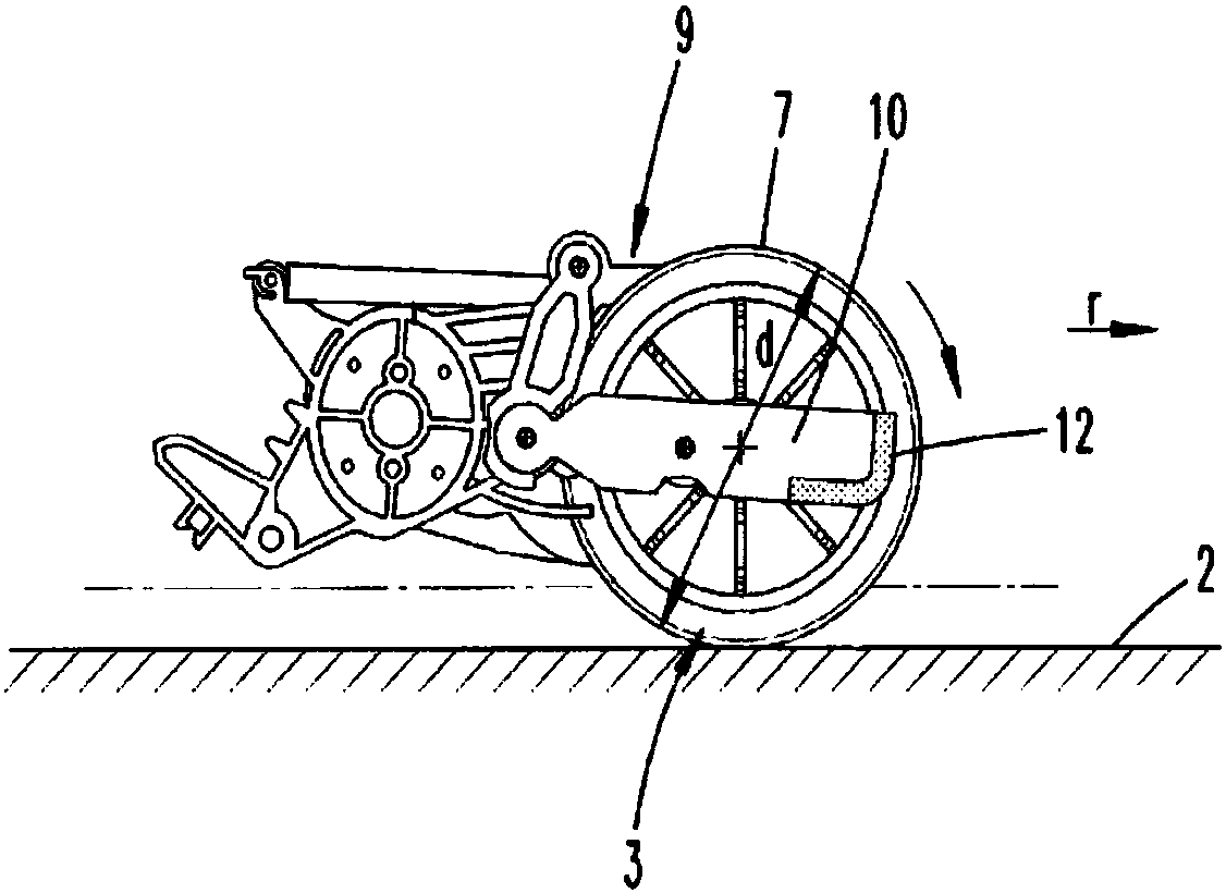
technical field [0001] The invention relates to a self-moving robot, which belongs to the technical field of small household appliance manufacturing. Background technique [0002] Self-mobile robots are widely used for their easy control and walking freely. However, due to the complexity of the working environment, various obstacles are usually encountered during the walking operation of self-mobile robots. Therefore, how to safely cross obstacles And to keep walking smoothly is the key issue to improve the work efficiency of self-mobile robots. [0003] figure 1 It is a structural schematic diagram of US8998215B2 prior art. Such as figure 1 As shown, this patent document discloses a device 9 for crossing obstacles in travel, which is preferably mounted on a floor-cleaning device with driven travel wheels 3 that can drive autonomously on a floor 2 . Specifically, a lifting component 10 is provided on the running wheel 3, and the front end surface 12 of the lifting compon...

Claims


Application Information

Patent Timeline
Patent Type & Authority Applications(China)
IPC IPC(8): B25J5/00B25J11/00B62D57/032
CPCB25J5/007B25J11/00B25J11/0085B62D57/032B25J5/00
Inventor 冯书鹏
Owner ECOVACS ROBOTICS (SUZHOU ) CO LTD
Why Eureka
Try Eureka