
Self-flashing traffic roadblock device

A technology for traffic roads and roadblocks, which is applied in the field of self-flashing traffic roadblocks, which can solve the problems of wasting electric energy, lack of warning function of luminous light strips, and no control measures, etc., and achieve the effect of enhancing stability

Inactive Publication Date: 2018-03-13
BEIJING JIAOTONG UNIV
View PDF8 Cites 7 Cited by
  • Summary
  • Abstract
  • Description
  • Claims
  • Application Information

AI Technical Summary

Problems solved by technology

[0007] The disadvantages of a solar traffic roadblock device adopted in the above-mentioned prior art are: the roadblock is a fixed roadblock, which is inconvenient to move and install; Compared with the luminous light strip, it lacks warning function, and the light strip is always on, without control measures, which wastes electric energy

Method used


Image

  • Self-flashing traffic roadblock device
  • Self-flashing traffic roadblock device

Examples


Embodiment 1

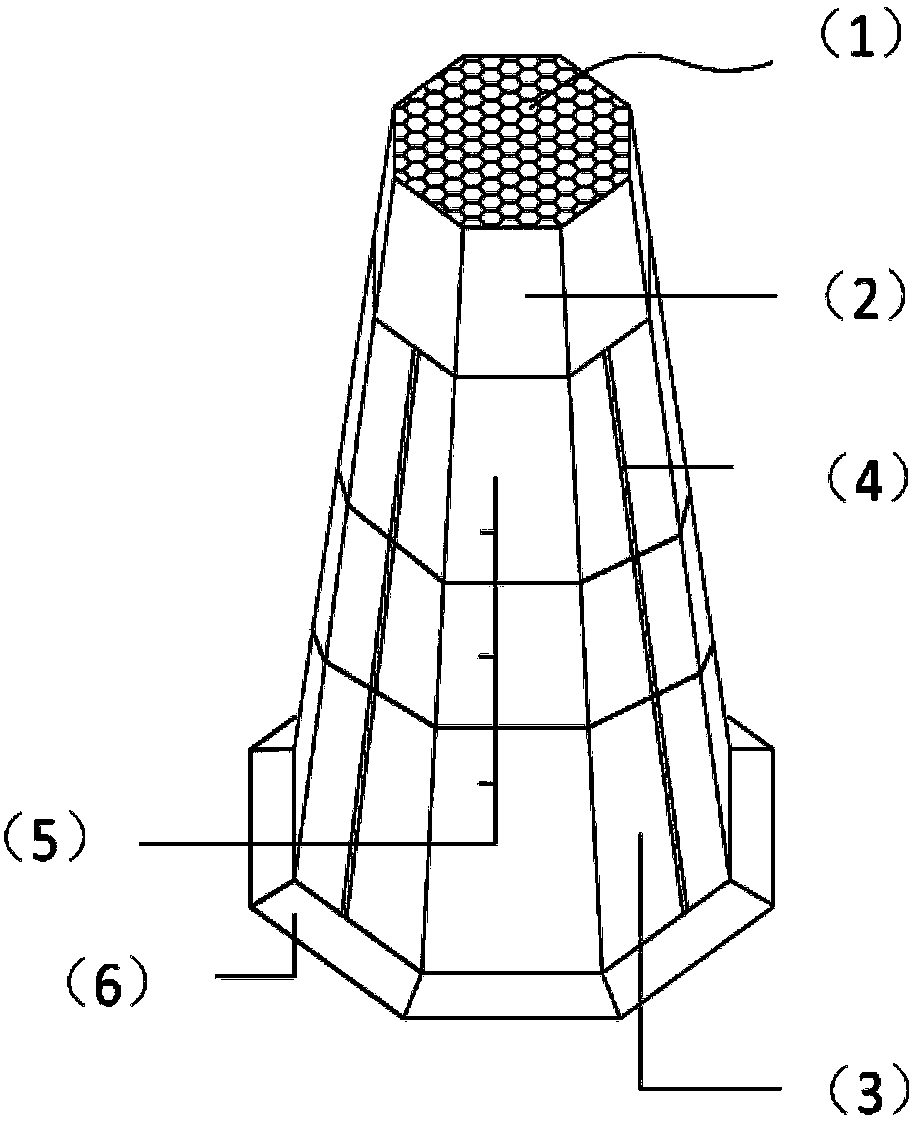
[0032] The embodiment of the present invention designs a self-flashing traffic roadblock device, which includes three parts: the top of the roadblock, the body of the roadblock and the base. The light strip, solar panel, battery and control circuit are combined with the roadblock. During use, the solar panel is used to and batteries provide power for the roadblock device; set self-flashing light strips and reflective layers on the surface of the device to enhance the warning effect of roadblocks; the interior of the device is designed to be hollow and the base is equipped with a water injection function, on the basis of ensuring that the device as a whole is light and easy to stack Enhanced stability.

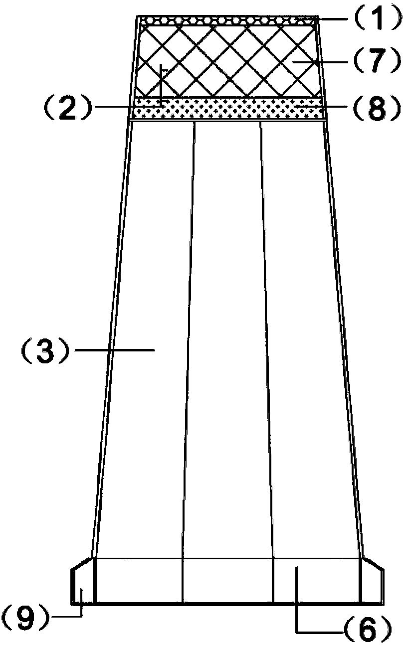
[0033] This embodiment provides a schematic diagram of the external structure of a self-flashing traffic barrier device as figure 1 As shown, it mainly includes three parts: a barricade top 2, a barricade body 3 and a base 6, the base 6 is located below the barricade body 3, th...

Embodiment 2

[0053] This embodiment provides a self-flashing traffic barricade device, including three parts: a barricade top, a barricade body and a base. The barricade top is located above the barricade body and is fixedly connected with the barricade body by bolts. It is a hollow connected cavity, which can be filled with water to increase the gravity of the barricade itself, enhance stability, and is not easy to topple over. Dumping water when moving can reduce the self-weight of the barricade and facilitate transportation.

[0054] The roadblock is in the shape of a regular octagonal truncated pyramid as a whole, with a regular octagonal structure in cross section and a hollow interior, allowing multiple roadblocks to be stacked. The top of the barricade is equipped with solar panels, batteries, circuit boards and protective covers; the four outer surfaces of the barricade body are provided with light strips, and the batteries, circuit boards and light strips are connected through powe...


PUM


Abstract

An embodiment of the invention provides a self-flashing traffic barrier device. The device includes: a barricade top, a barricade body and a base, the base is located under the barricade body, and is integrated with the barricade body, the barricade top is fixedly connected with the barricade body, the barricade is in the shape of a regular octagonal frustum pyramid, and the interior is hollow; the barricade top Install solar panels, batteries, circuit boards and protective covers, set up light strips on the four outer surfaces of the barricade body, and set light-transmitting condenser covers outside the light strips. The light strips are connected to the battery and the circuit board through power connectors, and the battery It is electrically connected with the solar panel; the base is a hollow cavity with a circular water injection port with a piston; the other four outer surfaces of the barricade body and the outer surface of the base are pasted or sprayed with reflective materials. The present invention has exquisite appearance, simple structure, reasonable design, flexible layout, convenient transportation, energy saving and environmental protection, and can meet the use requirements of different sites.

Description

technical field [0001] The invention relates to the technical field of traffic roadblocks, in particular to a self-flashing traffic roadblock device. Background technique [0002] Along with improving constantly of people's living standard, the use of vehicle is more and more extensive, and the roadblock that is used for restricting the passage of vehicle, parks and plays warning role when running into an emergency also plays a pivotal role. At present, the commonly used road barriers mainly include two forms, namely fixed barriers and movable barriers, which are widely used in urban traffic, highways, parking lots for large conference venues, schools and airports. [0003] A kind of barricade device that adopts in the prior art: generally all is passive luminescence, promptly reflects light with prism or reflects light with fluorescent cloth. [0004] The shortcoming of a kind of roadblock device that adopts in the above-mentioned prior art is: the device that reflects lig...

Claims


Application Information

Patent Timeline
Patent Type & Authority Applications(China)
IPC IPC(8): E01F13/00E01F9/615E01F9/619
CPCE01F13/00E01F9/617E01F9/619
Inventor 秦晓春张楠
Owner BEIJING JIAOTONG UNIV
Learn More