Thermosyphon heat dissipation combined switch cabinet

A combined switchgear technology, applied in substation/switch layout details, substation/switchgear cooling/ventilation, electrical components, etc., can solve the problems of wasted transportation space, waste, inconvenient installation and combination, etc., and improve the convenience of use Sex, easy to install and disassemble, and easy to dissipate heat

Active Publication Date: 2020-05-05
ANHUI MINGYUAN POWER EQUIP MFR
View PDF6 Cites 2 Cited by
  • Summary
  • Abstract
  • Description
  • Claims
  • Application Information

AI Technical Summary

Problems solved by technology

The applicant found that because the switchgear is a hollow shell structure, the volume occupied by the finished switchgear is often large during transportation, which wastes transportation space and is easily damaged by collision during the moving process. However, if it is transported in a semi-finished state, the ordinary switchgear Cabinets often need to be installed and assembled by welding or screws. The installation steps are cumbersome and require a high technical level, which is not convenient for installation and assembly. In addition, it is difficult to repair and replace when a part of the switch cabinet is damaged in the permanent assembly installation method. The entire switchgear needs to be replaced, which is wasteful

Method used


Image

  • Thermosyphon heat dissipation combined switch cabinet
  • Thermosyphon heat dissipation combined switch cabinet
  • Thermosyphon heat dissipation combined switch cabinet

Examples


Embodiment Construction

[0034] In order to make the object, technical solution and advantages of the present invention clearer, the present invention will be described in further detail below in conjunction with specific embodiments and with reference to the accompanying drawings.

[0035] It should be noted that all expressions using "first" and "second" in the embodiments of the present invention are to distinguish two entities with the same name but different parameters or parameters that are not the same, see "first" and "second" It is only for the convenience of expression, and should not be construed as a limitation on the embodiments of the present invention, which will not be described one by one in the subsequent embodiments.

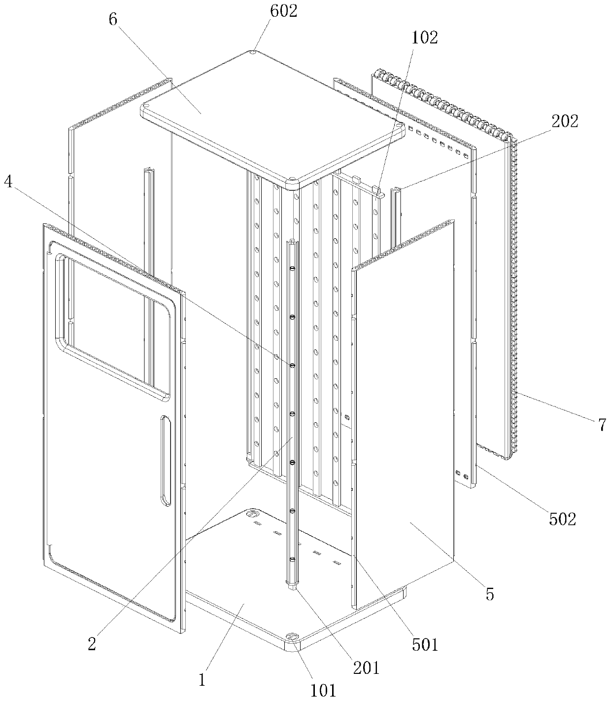
[0036] As an embodiment, a thermosiphon heat dissipation combined switchgear includes:

[0037] The bottom plate 1 is provided with a bottom notch 101 on the top surface, and a mounting frame 102 is vertically provided at the center;

[0038] The corner bracket 2 is ...


PUM


Abstract

The invention discloses a thermosyphon heat dissipation combined type switch cabinet. The device comprises a bottom plate. A bottom notch is arranged in the top. A mounting bracket is vertically arranged at the center. The device comprises a corner bracket which is vertically arranged above the bottom plate. A bottom connecting insertion block is arranged at the bottom end of the corner bracket. The corner bracket is connected with the bottom notch through the bottom connecting insertion block. A top end connecting hole is formed in the top of the corner bracket, and an embedding groove is formed in the middle of the corner bracket. The device comprises a locking block which is arranged in the middle of the embedding groove, and a locking magnet is arranged on the rear side of the lockingblock. According to the invention, the design of a split structure is adopted; the whole switch cabinet is divided into the bottom plate, the corner bracket, side face supporting plates and a top cover plate; the plates are all of plane structures and are convenient to stack, transport and move, meanwhile, embedded connection structures are arranged between the plates and can be manually installed, spliced and fixed; the locking structures can be conveniently and manually unlocked; the switch cabinet is convenient to install and detach; and the use convenience of the switch cabinet is improved.

Description

technical field [0001] The invention relates to electrical equipment, in particular to a thermosiphon heat dissipation combined switchgear. Background technique [0002] The switchgear is a kind of electrical equipment. The main function of the switchgear is to open and close, control and protect the electrical equipment during the process of power generation, transmission, distribution and power conversion in the power system. control switch, and then enter the sub-control switch, each branch is set according to its needs, such as instrumentation, automatic control, motor magnetic switch, various AC contactors, etc. Such as power plants, etc., some also have low cycle load shedding to ensure the main equipment. The applicant found that because the switchgear is a hollow shell structure, the volume occupied by the finished switchgear is often large during transportation, which wastes transportation space and is easily damaged by collision during the moving process. However,...

Claims


Application Information

Patent Timeline
Patent Type & Authority Applications(China)
IPC IPC(8): H02B1/30H02B1/56
CPCH02B1/301H02B1/565
Inventor 范文君吴桢
Owner ANHUI MINGYUAN POWER EQUIP MFR
Why Eureka
Try Eureka