
Truss load-bearing platform structure of three-pipe telescopic chimney

A load-bearing platform and chimney technology, which is applied in the field of chimneys of thermal power plants, can solve the problems of large area occupation, unfavorable costs, and poor engineering economy, and achieve the effects of reducing the amount of reinforced concrete, improving mechanical performance, and saving costs

Active Publication Date: 2020-06-05
四川电力设计咨询有限责任公司
View PDF7 Cites 0 Cited by
  • Summary
  • Abstract
  • Description
  • Claims
  • Application Information

AI Technical Summary

Problems solved by technology

[0003] The above-mentioned implementation has the following problems: the triangle formed by the main girder layout occupies a large area, which makes the diameter of the outer cylinder larger, the required materials and construction volume increase accordingly, and the project economy is poor; the section size of the solid-web main girder is relatively large Therefore, it is necessary to open a large hole in the wall of the outer cylinder, which is not good for the construction and the mechanical performance of the outer cylinder; for the large-diameter telescopic chimney, the strength utilization efficiency of the solid-web beam is very low when the disturbance is satisfied. Not conducive to saving costs

Method used


Image

  • Truss load-bearing platform structure of three-pipe telescopic chimney
  • Truss load-bearing platform structure of three-pipe telescopic chimney
  • Truss load-bearing platform structure of three-pipe telescopic chimney

Examples


Embodiment Construction

[0016] Below in conjunction with accompanying drawing and embodiment the present invention is further described:

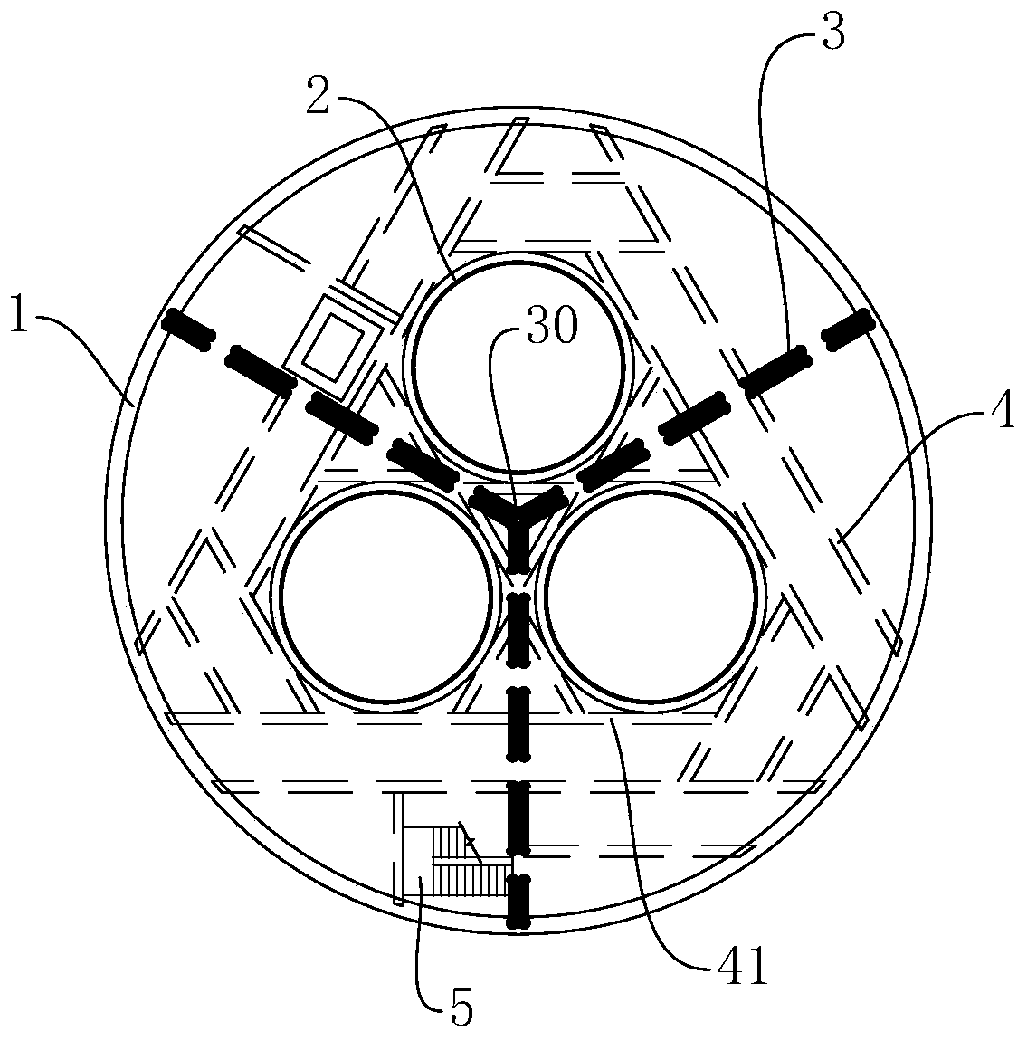
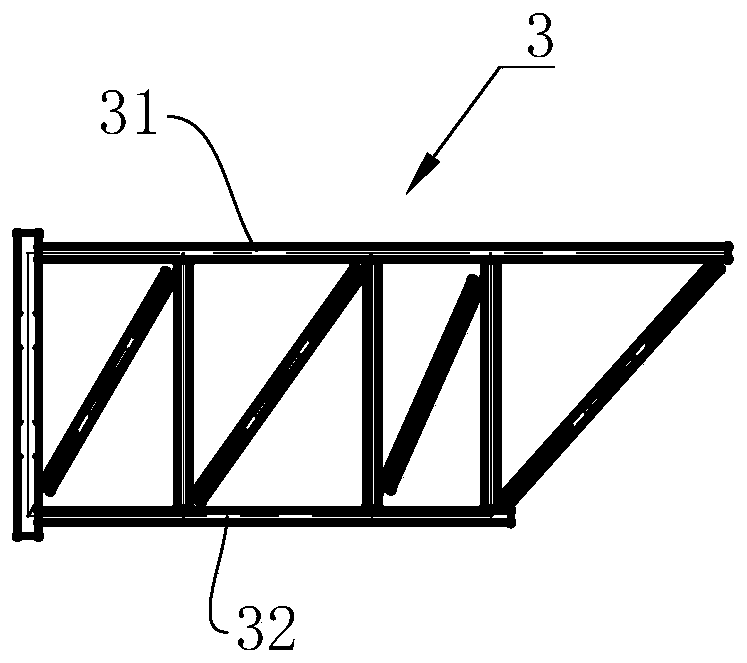
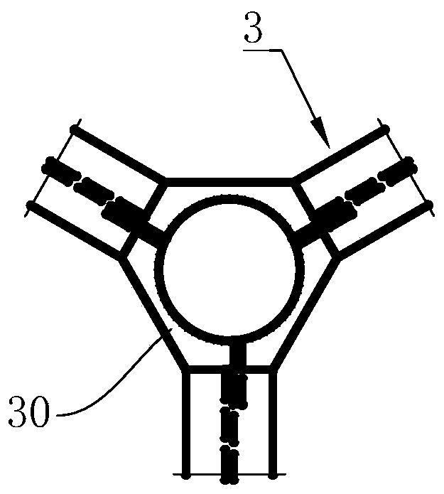
[0017] The truss load-bearing platform structure of the three-pipe telescopic chimney includes a chimney outer cylinder 1, and three chimney inner cylinders 2 are arranged inside the chimney outer cylinder 1, and the cross-sectional circle centers of the three chimney inner cylinders 2 are along the corner points of an equilateral triangle. The layout also includes three main girders 3, the main girders 3 include an upper chord 31 and a lower chord 32, and a plurality of web members are connected between the upper chord 31 and the lower chord 32, and form a truss structure; the main girder One end of 3 is connected to the inner wall of the chimney outer cylinder 1, the other end of the main beam 3 is located at the center of the section of the chimney outer cylinder 1, and is connected with the ends of the other two main beams 3, and the three main beams 3 connect ...


PUM


Abstract

The invention relates to a bearing platform structure of a three-tube sleeve type chimney. The bearing platform structure comprises a chimney outer cylinder, and three chimney inner cylinders are arranged in the chimney outer cylinder. The bearing platform structure further comprises three main beams which are of truss structures; one end of each main beam is connected to the inner wall of the chimney outer chimney, and the other end of each main beam is located at the circle center of the section of the chimney outer cylinder and is connected with the end parts of the other two main beams; the three main beams divide the section of the chimney outer cylinder into three fan-shaped areas, and each chimney inner cylinder is arranged in the corresponding fan-shaped area; the fan-shaped areasare further provided with a plurality of secondary beams, the secondary beams are arranged around the chimney inner cylinders and are connected with the chimney inner cylinders; and the main beams and / or the secondary beams are further connected with a shaking device used for maintaining the horizontal positions of the chimney inner cylinders. According to the bearing platform structure, the threemain beams of the truss structures are adopted as the bearing platform girders, one ends of the main beams are connected with the outer cylinder, the other ends of the main beams are connected to form a triangular structure, the outlet diameter of the outer cylinder can be reduced, the use amount of reinforced concrete for the outer cylinder and the use amount of steel bars for the bearing platform are reduced, the cost is saved, and hoisting is more convenient.

Description

technical field [0001] The invention relates to a chimney of a thermal power plant, in particular to a truss load-bearing platform structure of a three-pipe sleeve type chimney. Background technique [0002] At present, three-pipe sleeve chimneys are widely used in thermal power plants. Support the weight of the inner cylinder and keep the horizontal position of the inner cylinder stable. Usually, the load-bearing platform uses solid-web steel beams to penetrate the outer cylinder of the chimney. For example, three solid-web steel beams are used as the main beam. The outer cylinder is connected, and then multiple secondary beams are set between the main beam and the chimney outer cylinder to fix the inner cylinder. [0003] The above-mentioned implementation has the following problems: the triangle formed by the main girder layout occupies a large area, which makes the diameter of the outer cylinder larger, the required materials and construction volume increase accordingl...

Claims


Application Information

Patent Timeline
Patent Type & Authority Patents(China)
IPC IPC(8): E04H12/28
CPCE04H12/28
Inventor 龚节福陈刚漆桧李龙华
Owner 四川电力设计咨询有限责任公司
Learn More