Micro fluid control device

A fluid control device, a miniature technology, used in liquid variable volume machinery, pumps with flexible working elements, machines/engines, etc., which can solve problems such as increased noise, energy loss, and reduced contact interference.

Active Publication Date: 2018-03-13
MICROJET TECH
View PDF8 Cites 5 Cited by
  • Summary
  • Abstract
  • Description
  • Claims
  • Application Information

AI Technical Summary

Problems solved by technology

[0005] However, a recessed stepped space is formed between the outer frame 122' and the suspension plate 121', and then through the aforementioned glue layer 13' that fills the gap h0' between the outer frame 122' and the resonant plate 142', By maintaining the required depth h' of the compression chamber 10', although the suspension plate 121' and the resonance plate 142' can be kept at an appropriate distance, and the contact and interference between each other can be reduced, the outer frame 122' is made of a metal material , has a certain degree of rigidity, and the conventional practice here is to maintain the height of the outer frame 122' with a step difference height and combine it with the adhesive layer 13' between the resonant plates 142', but for this, a section occupies 2 / 3 of the height The metal frame 122' is used to match a section of adhesive layer 13' which accounts for 1 / 3 of the height to achieve the depth h' required by the compression chamber 10'. This configuration is not only more rigid, but the suspension plate 121' is vertically Directional vibration cannot effectively absorb other interference vibrations generated during vibration, so it will cause energy loss and increase noise. The noise problem is also one of the reasons for product failure.

Method used


Image

  • Micro fluid control device
  • Micro fluid control device
  • Micro fluid control device

Examples


Embodiment Construction

[0064] Some typical embodiments embodying the features and advantages of the present invention will be described in detail in the description in the following paragraphs. It should be understood that the present invention can have various changes in different aspects without departing from the scope of the present invention, and the description and drawings therein are used as illustrations in nature and not for limitation this invention.

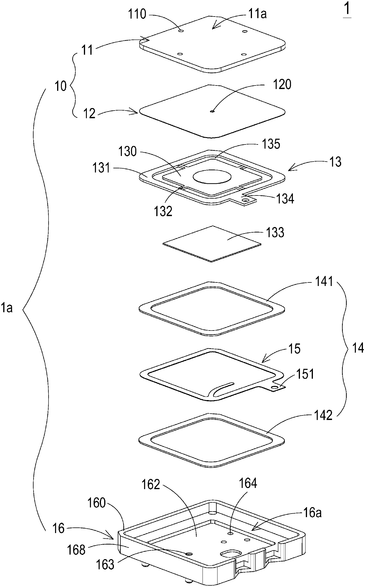
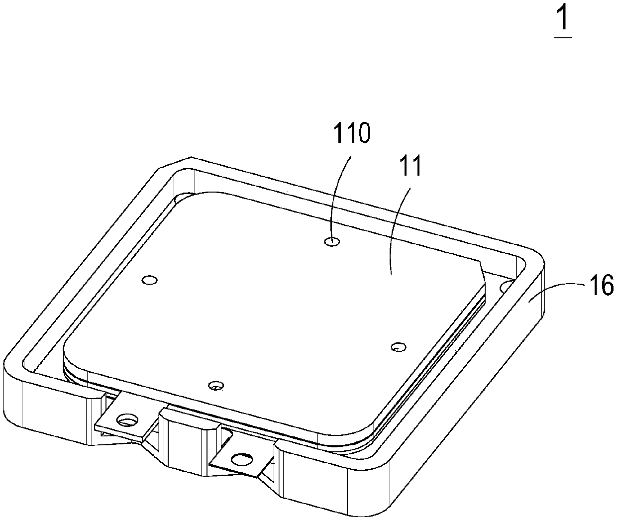
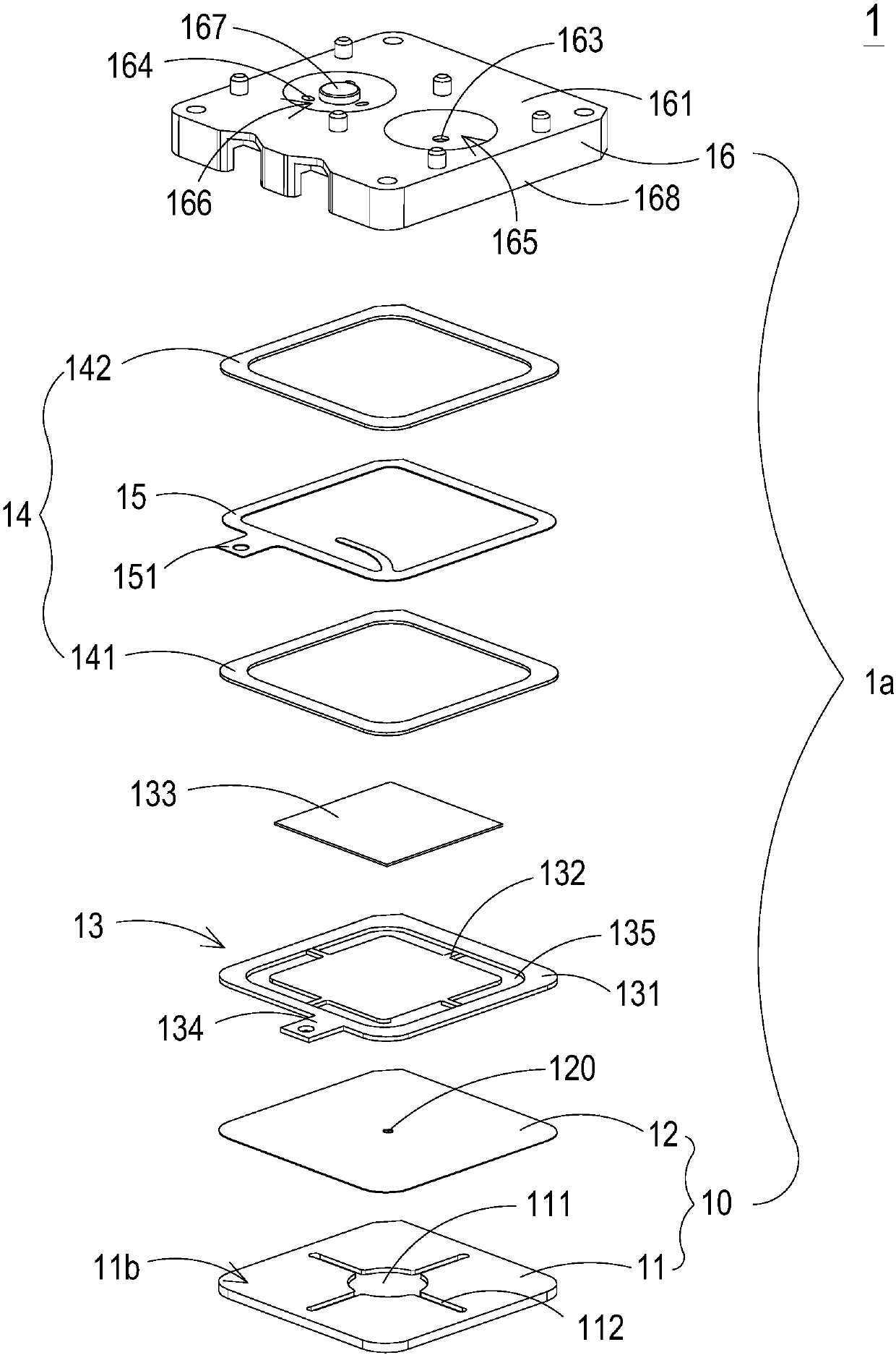
[0065] The micro-fluid control device 1 of the present invention can be applied in industries such as medical biotechnology, energy, computer technology or printing to transmit fluids, but not limited thereto. see Figure 1A , Figure 1B , Figure 2A and Figure 2B , Figure 1A It is a schematic diagram of the front exploded structure of the microfluidic control device in a preferred embodiment of the present invention, Figure 1B for Figure 1A The schematic diagram of the front assembly structure of the microfluidic control device ...


PUM


Abstract

A micro fluid control device comprises a piezoelectric actuator and a shell. The piezoelectric actuator is provided with a suspension plate, an outer frame, a support and a piezoelectric ceramic plate. The suspension plate is in a square form and is provided with a first surface and a second surface, and the second surface is provided with a convex part. The outer frame is arranged outside the suspension plate in a surrounding mode and is also provided with a first surface and a second surface. The areas except the second surface of the outer frame and the convex part of the second surface ofthe suspension plate are all coplanar. The shell comprises a gas collection plate and a base. The gas collection plate is of a frame structure with a holding space. The base is formed by connecting agas inlet plate and a resonantor and is arranged in the holding space so as to close the piezoelectric actuator. A glue layer is arranged between the second surface of the outer frame of the piezoelectric actuator and the resonantor of the base, so that a needed depth of a compression cavity is maintained between the piezoelectric actuator and the resonantor.

Description

technical field [0001] The invention relates to a miniature fluid control device, in particular to a miniature, ultra-thin and silent micro fluid control device. Background technique [0002] At present, in various fields, whether it is medicine, computer technology, printing, energy and other industries, products are developing towards refinement and miniaturization. Among them, micro pumps, sprayers, inkjet heads, industrial printing devices and other products contain fluid delivery structures. Its key technology, therefore, how to break through its technical bottleneck through innovative structure is an important content of development. [0003] For example, in the pharmaceutical industry, many instruments or equipment that need to be driven by pneumatic power usually use traditional motors and pneumatic valves to achieve the purpose of gas delivery. However, limited by the volume limitations of such traditional motors and gas valves, it is difficult to reduce the overal...

Claims


Application Information

Patent Timeline
Patent Type & Authority Applications(China)
IPC IPC(8): F04B43/04
CPCF04B43/046
Inventor 韩永隆黄启峰陈世昌廖家淯廖鸿信黄哲威陈寿宏
Owner MICROJET TECH
Why Eureka
Try Eureka