Electric connector for flat conductor

An electrical connector, a flat type technology, applied in the field of electrical connectors for flat conductors, can solve the problems of reduced reliability of the connection state between terminals and flat conductors, achieve stable contact, and reduce manufacturing and assembly errors

Inactive Publication Date: 2012-01-25
HIROSE ELECTRIC GROUP
View PDF7 Cites 11 Cited by
  • Summary
  • Abstract
  • Description
  • Claims
  • Application Information

AI Technical Summary

Problems solved by technology

This will reduce the reliability of the connection state between the terminal and the flat conductor

Method used


Image

  • Electric connector for flat conductor
  • Electric connector for flat conductor
  • Electric connector for flat conductor

Examples


Embodiment Construction

[0042] One embodiment of the present invention will be described below with reference to the drawings.

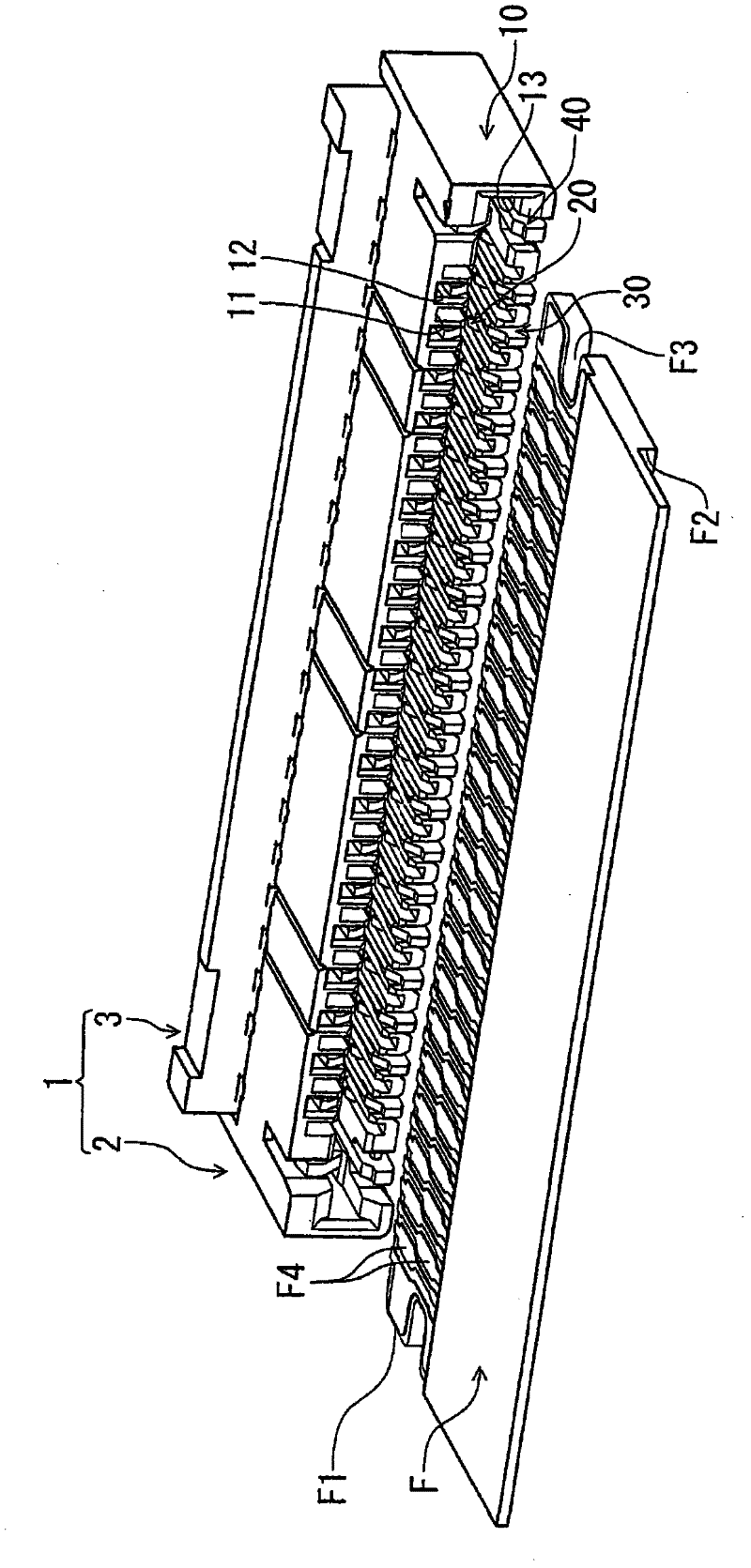
[0043] exist figure 1 Among them, symbol 1 is the connector of this embodiment, and symbol F is a flat conductor connected to the connector 1 .

[0044] The flat conductor F has a connecting portion connected to the above-mentioned connector 1 at its front end (the upper right edge in the figure), and extends longly toward the rear. Illustration omitted. In the present embodiment, the above-mentioned flat conductor F removes the covering portion on the upper surface of the tip portion to expose the connection circuit portion F1 to form a connection portion. In order to improve the strength when connecting with the connector, a reinforcing sheet F2 is provided on the lower surface of the connecting part.

[0045] At the connection portion of the above-mentioned flat conductor F, engaged portions F3 are formed by notches on both side edges in the width direction. Letting ...


PUM


Abstract

An electric connector for a flat conductor comprises two kinds of terminals with different assembling directions towards a shell and can greatly reduce position error of cam parts. In the flat type electric connector for the conductor, an attaching part (38A) of a second terminal (30) attached with the cam is arranged at a position which is the same with a lower edge of a position limiting part (18B) or therebelow, an attaching part (28A) of a first terminal (20) is arranged above the attaching part (38A) of the second terminal (30), a first cam part (55) and a second cam part (56) of a movable construction member (3) can rotate around a common axes, the movable construction member (3) is provided with upper cam edges (55B), (56B) and lower cam edges (55A), (56A) which are abutted against upper arm parts and lower arm parts of the first terminal and the second terminal, the lower cam edges (55A), (56A) of the first cam part (55) and the second cam part (56) can form that when the movable construction member (3) turns towards a closed position, the difference of radius lengths of the cams which are movably contacted with the lower arm part within a movable contacting range and in the optional same angle positions is a fixed value.

Description

technical field [0001] The invention relates to an electrical connector for flat conductors. Background technique [0002] In the connector disclosed in Patent Document 1, the terminal has an upper arm portion and a lower arm portion extending in the front-rear direction, and is formed in a horizontal H shape in which both are connected by a connecting portion. In this Patent Document 1, two types of terminals are formed, both of which form a horizontal H shape, one type of terminal is assembled toward the housing from the front, and the other type of terminal is assembled toward the housing from the rear. Due to the difference in the assembling direction, the details including the connecting portion for connecting to the circuit board are different, but the two types of terminals have basically the same shape in terms of forming a horizontal H shape. In the assembled state toward the housing, insert the FPC as the object to be connected between the upper arm and the lower ...

Claims


Application Information

Patent Timeline
Patent Type & Authority Applications(China)
IPC IPC(8): H01R12/77H01R13/02H01R13/62
CPCH01R12/774H01R13/629H01R13/639
Inventor 和田俊太郎
Owner HIROSE ELECTRIC GROUP
Why Eureka
Try Eureka