Method for a synchronous range shift on an electronically controlled two-speed transfer case with an electronically controlled engine and transmission

A transfer case and transmission technology, which is applied in the direction of vehicle gearbox, control device, transmission control, etc., can solve the problem of increasing the probability of the vehicle being stuck

Inactive Publication Date: 2018-03-13
GM GLOBAL TECH OPERATIONS LLC
View PDF3 Cites 3 Cited by
  • Summary
  • Abstract
  • Description
  • Claims
  • Application Information

AI Technical Summary

Problems solved by technology

Stopping a vehicle increases the chance of the vehicle getting stuck

Method used


Image

  • Method for a synchronous range shift on an electronically controlled two-speed transfer case with an electronically controlled engine and transmission
  • Method for a synchronous range shift on an electronically controlled two-speed transfer case with an electronically controlled engine and transmission
  • Method for a synchronous range shift on an electronically controlled two-speed transfer case with an electronically controlled engine and transmission

Examples


example 1

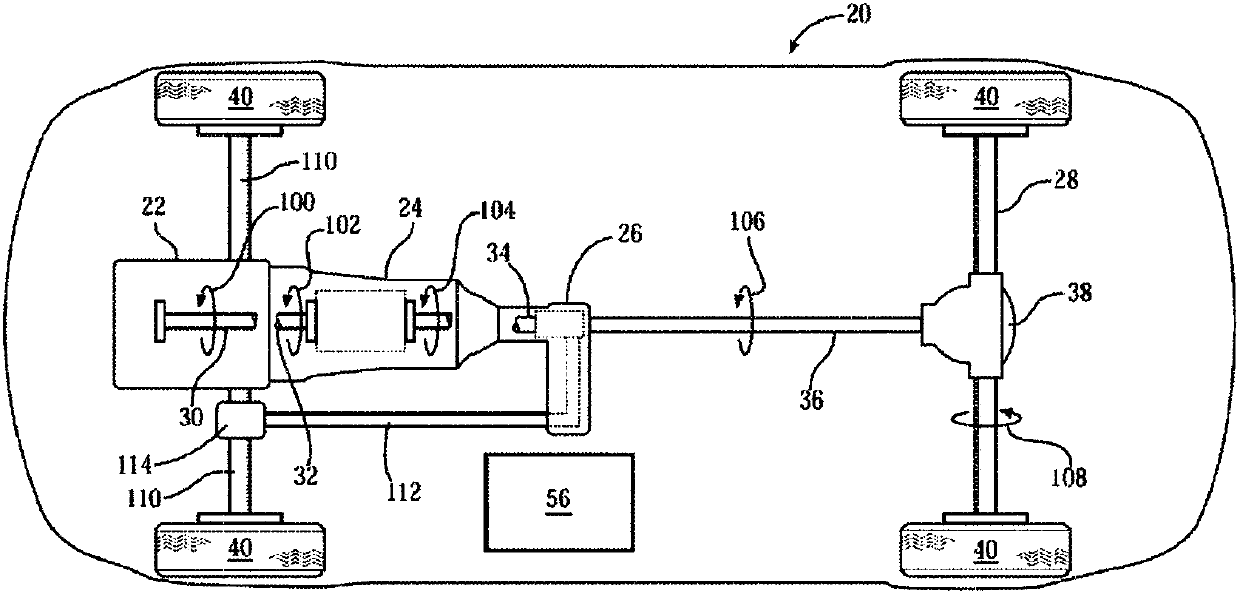
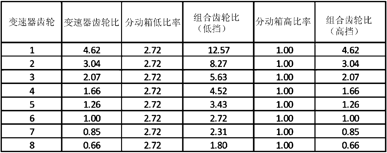
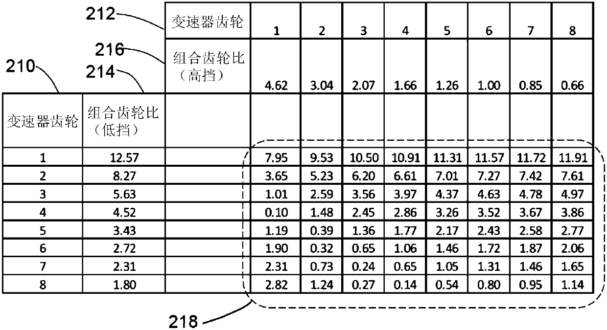
[0033] have figure 2 The vehicle with the exemplary gear ratios shown in is operated with the transmission in fourth gear and the transfer case in its low range, where the transmission input shaft speed 102 is 2500 rpm. Look image 3 or Figure 4 In column 214, the combined gear ratio of transmission input shaft speed 102 to transfer case output speed 106 is 4.52. Transfer case output speed 106 is found by dividing (transmission input shaft speed 102) by (combined gear ratio), which equals 2500 / 4.52, or 553 rpm. This can be done with the transfer case in its high range and the transmission in first gear (combined gear ratio = from image 3 or Figure 4 The same transfer case output speed 106 of 553 rpm is achieved by 4.62 of the row 216 of , where the transmission input shaft speed 102 is equal to 2555 rpm (2555 / 4.62=553). The ratio of transmission input shaft speed 102 resulting in the same transfer case output speed 106 can be calculated as 2555 / 2500, or 1.022. In oth...

example 2

[0035] have figure 2 The vehicle with the exemplary gear ratios shown in is operated with the transmission in second gear and the transfer case in its high gear, where the transmission input shaft speed 102 is 2500 rpm. Look image 3 or Figure 4 The combined gear ratio of transmission input shaft speed 102 to transfer case output speed 106 is 3.04 across row 216 . Transfer case output speed 106 is found by dividing (transmission input shaft speed 102) by (combined gear ratio), which equals 2500 / 3.04, or 822 rpm. This can be done with the transfer case in its low range and the transmission in fifth gear (combined gear ratio = from image 3 or Figure 4 3.43 of column 214 of ) achieves the same transfer case output speed 106 of 822 rpm, where the transmission input shaft speed 102 is equal to 2819 rpm (2819 / 3.43=822). The ratio of transmission input shaft speed 102 resulting in the same transfer case output speed 106 can be calculated as 2819 / 2500, or 1.12. In other word...

example 3

[0037] In this example, the same initial conditions as presented above in Example 2 will be used. have figure 2 The vehicle with the exemplary gear ratios shown in is operated with the transmission in second gear and the transfer case in its high gear, where the transmission input shaft speed 102 is 2500 rpm. Look image 3 or Figure 4 The combined gear ratio of transmission input shaft speed 102 to transfer case output speed 106 is 3.04 across row 216 . Transfer case output speed 106 is found by dividing (transmission input shaft speed 102) by (combined gear ratio), which equals 2500 / 3.04, or 822 rpm. In this example, it could be possible with the transfer case in its low range and the transmission in sixth gear (combined gear ratio = from image 3 or Figure 4 2.72 of the column 214 of ) achieves the same transfer case output speed 106 of 822 rpm, where the transmission input shaft speed 102 is equal to 2819 rpm (2235 / 2.72=822). The ratio of transmission input shaft s...


PUM


Abstract

A method for shifting between a low speed range and a high speed range for a two-speed transfer case in a four-wheel drive vehicle includes determining a target transmission gear ratio and a desired transfer case range based on the current vehicle speed and the initial transfer case range. The transmission is shifted to the target transmission gear ratio when it is determined that the vehicle speed is in an appropriate range. The transfer case input torque is reduced to a minimum value, and the transfer case is shifted to neutral. The method further includes adjusting the engine speed and transmission gear setting to control the transmission output shaft speed to a desired range. The transfer case is shifted from neutral to the desired transfer case range when the transmission output shaftspeed is within the desired range of transmission output shaft speed.

Description

technical field [0001] The present invention generally relates to a method for synchronously shifting gears between high and low gears of a transfer case of a vehicle. Background technique [0002] The background description provided herein is for the purpose of generally presenting the context of the disclosure. The work of the presently named inventors, to the extent described in this Background section, and aspects of this specification that do not qualify as prior art at the time of filing are neither expressly nor implicitly admitted as prior art to the present disclosure. [0003] A transfer case for a 4× vehicle is typically capable of operating in two different gear ratios, often referred to as high and low. Typically, shifting between high and low gears requires stopping the vehicle and shifting the vehicle transmission into neutral. Bringing the vehicle to a stop increases the chances of the vehicle getting stuck. Performing 4x4 shifts while the vehicle is movi...

Claims


Application Information

Patent Timeline
Patent Type & Authority Applications(China)
IPC IPC(8): F16H61/02F16H61/04
CPCF16H61/0204F16H61/04F16H61/0437B60K2023/0825B60K5/02B60K17/3467B60K23/08F16H2200/0017F16H2200/0034B60W10/06B60W10/11B60W10/14B60W30/188B60W50/14B60W2510/1005B60W2520/10B60W2710/0644B60W2710/0666B60W2710/1005B60W2710/1038F16H3/46F16H61/0213F16H2200/2005
Inventor P·J·贾尔斯S·D·霍夫曼A·卡波比安科
Owner GM GLOBAL TECH OPERATIONS LLC
Why Eureka
Try Eureka