Control device of automatic transmission

A technology of automatic transmission and control device, applied in the direction of transmission device control, elements with teeth, belt/chain/gear, etc., can solve the problems of rising manufacturing cost and increasing failure rate.

A technology of automatic transmission and control device, applied in the direction of transmission device control, elements with teeth, belt/chain/gear, etc., can solve the problems of rising manufacturing cost and increasing failure rate.

CN107795684AInactive Publication Date: 2018-03-13MAZDA MOTOR CORP

Image

  • Control device of automatic transmission
  • Control device of automatic transmission
  • Control device of automatic transmission

Examples


no. 1 approach

[0024] 1. Structure of vehicle 1

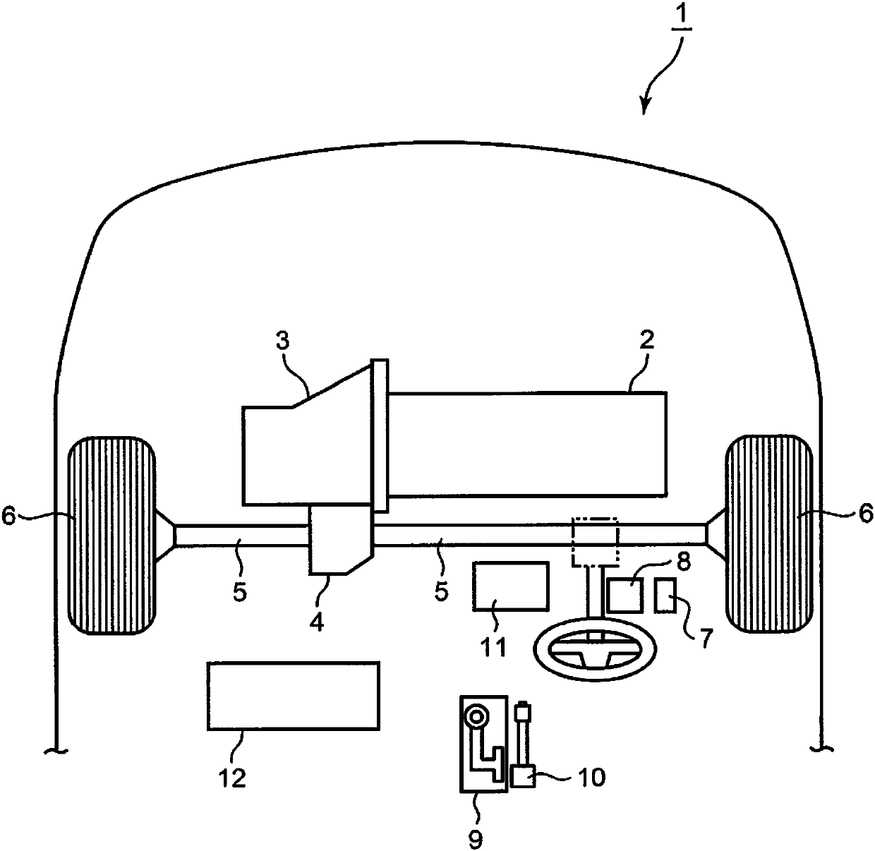
[0025] use figure 1 The configuration of the vehicle 1 according to the present embodiment will be described. figure 1 It is a schematic diagram showing a partial structure of the vehicle 1 .

[0026] Such as figure 1 As shown, a vehicle 1 has an engine 2 , an automatic transmission 3 , a differential gear 4 , a drive shaft 5 and wheels 6 .

[0027] The engine 2 is provided as a driving source in the vehicle 1 and is an internal combustion engine that obtains power by internally combusting fuel. The form of the engine 2 is not particularly limited, and as an example, a four-stroke multi-cylinder gasoline engine can be used. A crankshaft of the engine 2 is connected to an automatic transmission 3 .

[0028] The automatic transmission 3 is a continuously variable transmission or a planetary gear type automatic transmission that decelerates the rotation of the crankshaft of the engine 2 and transmits it to the drive shaft 5 . The vehicle 1...


PUM


Abstract

The invention relates to a control device of an automatic transmission. A shift position determination portion determines that operation of shifting a shift position from other range than a parking range to the parking range is conducted. A parking lock command portion causes a piston to maintain a state of being mechanically locked at a second position when the shift position is shifted to the parking range. An actuator drive command portion commands an actuator to drive the piston from the second position to a first position in a state where the position of the piston is mechanically lockedat the second position. A parking lock failure determination portion determines that the locking mechanism portion is in a failure in an unlocked state when the position of the piston goes out of thesecond position within a predetermined time after a command is issued. The device not only guarantees high reliability but also inhibits increase of manufacturing cost.

Description

technical field [0001] The invention relates to a control device for an automatic transmission in a shift-by-wire mode. Background technique [0002] The following structure is adopted in the automatic transmission of the shift-by-wire mode: a mechanical parking lock mechanism is provided to realize double insurance. Specifically, the lock-up mechanism is provided in such a way that the state other than the parking range can be maintained even if the hydraulic pressure drops during driving in the previous forward range. , even if the hydraulic pressure is activated, the parking state will not be released. [0003] In the above-mentioned parking lock mechanism section, it is necessary to provide a structure for detecting both a failure in a locked state and a failure in an unlocked (unlocked) state. Japanese Patent Laid-Open Publication No. 2007-303680 (patent document) discloses a configuration for detecting failure of the above-mentioned parking lock mechanism unit. The ...

Claims


Application Information

Patent Timeline
13 Mar 2018
Publication
CN107795684A
IPC
F16H63/34; F16H61/30
CPC
F16H61/30; F16H63/3483; F16H2061/308; F16H59/68; F16H2061/1208; F16H2061/1216; F16H61/12
Inventors
木村隆浩; 重中康夫