
Apparatus and method for detecting strength at leading-out terminal and sealing point of axial lead device

A technology of axial lead and strength detection, which is applied in the direction of measuring device, using stable torsion to test the strength of materials, strength characteristics, etc., can solve the problems of failing to meet the plumb requirements, static devices, etc., and achieve the goal of improving operability Effect

Pending Publication Date: 2018-03-13
JINAN JINGHENG ELECTRONICS
View PDF15 Cites 2 Cited by
  • Summary
  • Abstract
  • Description
  • Claims
  • Application Information

AI Technical Summary

Problems solved by technology

[0006] The technical problem to be solved by the present invention is to provide a device and method for detecting the strength of the lead-out end and the seal of an axial lead device, which solves the problem that the device cannot be stationary and cannot meet the plumb requirements when manually operating a vise or a torque wrench. And there is no other impact and other unfavorable problems such as the strength detection of the lead-out end of the device and the seal, which greatly improves the operability

Method used


Image

  • Apparatus and method for detecting strength at leading-out terminal and sealing point of axial lead device
  • Apparatus and method for detecting strength at leading-out terminal and sealing point of axial lead device
  • Apparatus and method for detecting strength at leading-out terminal and sealing point of axial lead device

Examples


Embodiment Construction

[0022] The present invention will be further described below in conjunction with the accompanying drawings and specific embodiments.

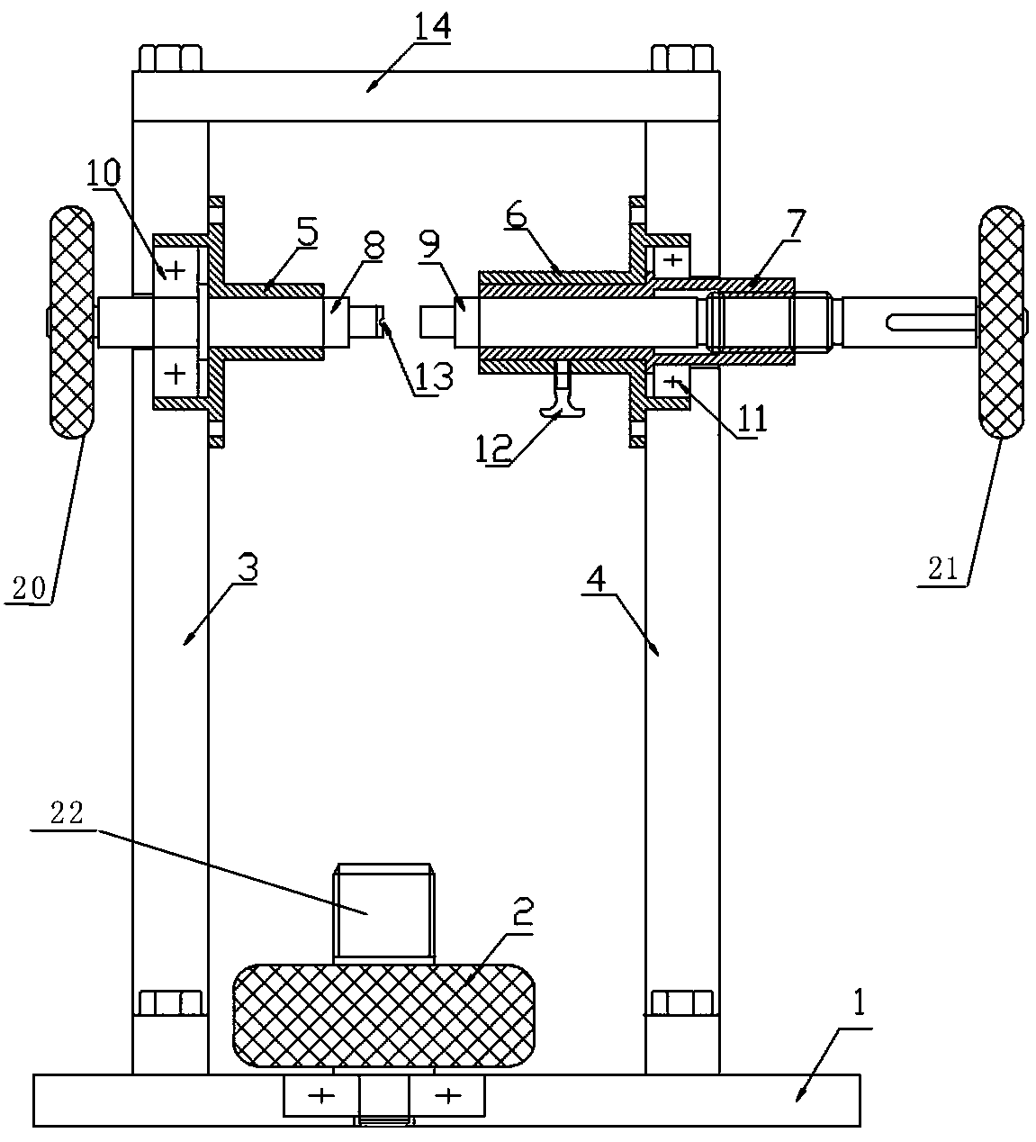
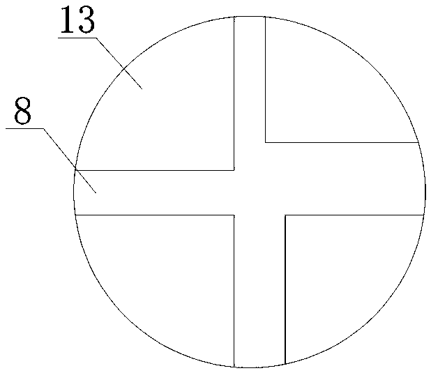
[0023] Such as figure 1 As shown, a device for detecting the strength of the lead-out end of an axis lead device and the seal, including a base plate 1, a rotary table 2 located on the base plate 1, and a left side plate 3 and a right side plate 4 installed vertically on the bottom plate, the left side The plate 3 is provided with a left shaft 8, a left bearing seat 5, a left pressure bearing 10, and a fastening cavity 13, and the right plate is provided with a right bearing seat 6, a sleeve 7, a right shaft 9, and a right Pressure bearing 11 and jack screw 12. A detection space is formed between the left side plate 3 and the right side plate 4. In this embodiment, for the convenience of description, the end of the left shaft 8 located in the detection space is called its right end, and the end not located in the detection space is called As...


PUM


Abstract

The invention discloses an apparatus and method for detecting strength at a leading-out terminal and a sealing point of an axial lead device. The device comprises a left side plate and a right side plate parallel to each other, wherein a detection space is formed between the left side plate and the right side plate; a left side shaft passing through the left side plate to enter the detection spaceis arranged on the left side plate; a right side shaft passing through the right side plate to enter the detection space is arranged on the right side plate; a fastening cavity for clamping an axialdevice lead or a tube shell is arranged at an end part, in the detection space, of the left side shaft; the left side shaft is in rotatable connection with the left side plate; the right side shaft isconnected with a drive component for driving the right side shaft to move linearly. The apparatus and method disclosed by the invention solve the problem that the device cannot be kept still and thusdoes not meet the vertical requirement during manual operation of a vince or torque spanner, and avoids other impact and the like unfavorable for strength detection at the leading-out terminal and sealing point of the device, thereby greatly improving the operability.

Description

technical field [0001] The invention relates to a device for detecting the strength of a lead-out end and a sealing part of an axial lead device, and also relates to a detection method based on the detection device. Background technique [0002] Such as figure 2 As shown, the axial leaded device includes two copper leads 15 , two solders 16 , two molybdenum electrodes 17 , a chip 18 and a package 19 . Two molybdenum electrodes 17 are respectively inserted from both ends of the shell 19 and are in contact with the chip 18, and two copper leads 15 are soldered to the center of the two molybdenum electrodes 17 with solder 16 respectively, and the diameter of the large end of the copper leads 15 is smaller than that of the molybdenum electrode 17 diameter. [0003] According to the "Semiconductor Device Test Methods and Procedures", it is necessary to measure the strength of the leads, welds and seals of the sintered axial lead devices, such as linear tensile resistance, metal...

Claims


Application Information

Patent Timeline
Patent Type & Authority Applications(China)
IPC IPC(8): G01N3/08G01N3/22G01N3/34
CPCG01N3/08G01N3/22G01N3/34G01N2203/0003G01N2203/0005G01N2203/0021G01N2203/0023G01N2203/0017G01N2203/0033G01N2203/0037
Inventor 时石王培祥田龙孙家高马德鹏郑明吕亮路滨滨管兴泽张明
Owner JINAN JINGHENG ELECTRONICS
Learn More