Automatic focusing lens module

A technology for auto-focusing and focusing lenses, applied to focusing devices, installations, optics, etc., can solve problems such as easy tilting, low material precision, and unsmooth rotation of the outer adjustment ring

Pending Publication Date: 2018-03-13
东莞市维斗科技股份有限公司
View PDF0 Cites 0 Cited by
  • Summary
  • Abstract
  • Description
  • Claims
  • Application Information

AI Technical Summary

Problems solved by technology

The slotted screw is machined, the slotted screw rubber sleeve is machined, and the outer adjustment cylinder is machined. The material has low precision and poor consistency.
In addition, in the prior art, the outer adjustment cylinder has only two hangers, which are distributed at 180°, so the outer adjustment cylinder is not

Method used


Image

  • Automatic focusing lens module
  • Automatic focusing lens module
  • Automatic focusing lens module

Examples


Embodiment 1

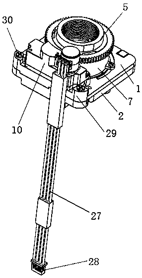
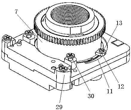
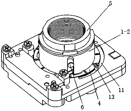
[0037] Such as figure 1 As shown, the embodiment of the present invention discloses an auto-focus focusing lens module, including a cover plate 1, such as Figure 6 As shown, the cover plate 1 includes a plate-shaped connecting portion 1-1, a through hole is provided in the middle of the plate-shaped connecting portion 1-1, and a cylindrical connecting portion 1-1 extending upward is provided in the through hole. 2. An IR-CUT assembly is arranged between the plate-shaped connecting part 1-1 and the fixing seat 2. The cylindrical connecting portion 1-2 is provided with more than two elongated holes extending up and down, and the inner side of the plate-shaped connecting portion 1-1 is provided with rectangular holes corresponding to the elongated holes and communicating with each other. A corrugated shrapnel placing groove 3 is provided on the plate-shaped connecting portion close to the cylindrical connecting portion, and a corrugated shrapnel 4 is arranged in the corrugated ...

Embodiment 2

[0049] The specific structure of the second embodiment differs from that of the first embodiment in that: the specific forms of the elastic device, the cylindrical connecting portion and the outer adjustment cylinder are different. In this embodiment, the same content as the embodiment will not be repeated.

[0050] Specifically, such as Figure 9-14 As shown, the embodiment of the present invention discloses an auto-focus focusing lens module, including a cover plate 1, and the cover plate 1 includes a plate-shaped connecting portion 1-1, and a through hole is arranged in the middle of the plate-shaped connecting portion 1-1. A cylindrical connecting portion 1-2 extending upward is provided in the through hole. The cylindrical connecting portion 1-2 is provided with three elongated holes extending up and down, the outer diameter of the picture frame 5 is equal to the inner diameter of the cylindrical connecting portion 1-2, and the radial direction of the picture frame 5 on ...


PUM


Abstract

An automatic focusing lens module disclosed by the present invention relates to the optical device technology field and comprises a cover plate, the cover plate comprises a plate-shaped connecting part, and the middle part of the plate-shaped connecting part is equipped with a through hole. A cylindrical connecting part extending upwards is arranged in the through hole, a lens frame is inserted inthe cylindrical connecting part and is used to place a lens, and an external adjusting cylinder is arranged at the outer side of the cylindrical connecting part and sleeves the cylindrical connectingpart. The external adjusting cylinder and the lens frame are connected via a connecting column, the external adjusting cylinder is used to drive the lens frame to move along a Z-axis, and an elasticdevice is arranged between the external adjusting cylinder and the plate-shaped connecting part, so that multiple sets of tolerance fit influencing the movement clearance of the Z-axis of the lens frame is reduced to one set of tolerance fit or zero set of tolerance fit, and accordingly, the situation that the movement clearance of the lens frame in the Z-axis is very small is guaranteed, and theclearance is between 0.03 mm and 0.05 mm or is 0.

Description

technical field [0001] The invention relates to the technical field of optical devices, in particular to an auto-focusing focusing lens module with a very small movement gap of a mirror frame (lens) on the Z axis. Background technique [0002] For existing lens modules, the theoretical value of the frame (lens) movement clearance on the Z axis is 0.045 mm to 0.125 mm, but the actual measured value is 0.08 mm to 0.12 mm. The z-axis movement clearance of the frame is determined by the combination of the slotted screw and the slotted screw sleeve, the screw sleeve and the outer adjustment tube chute (KM slot), the outer adjustment tube hanger and the cover plate hanger. The slotted screw is machined, the slotted screw rubber sleeve is machined, and the outer adjustment cylinder is machined. The material has low precision and poor consistency. In addition, in the prior art, the outer adjustment cylinder has only two hanging platforms, which are distributed at 180°, so the outer...

Claims


Application Information

Patent Timeline
IPC IPC(8): G02B7/09G02B7/02G02B7/00G03B13/36G03B17/14
CPCG02B7/006G02B7/022G02B7/09G03B13/36G03B17/14
Inventor 钟木生杨俊文赵少伟
Owner 东莞市维斗科技股份有限公司
Why Eureka
Try Eureka