Transmission shaft body structure

A transmission shaft and shaft body technology, applied in the field of transmission, can solve the problems of unreasonable structural design of the transmission shaft body, inability to perform variable frequency speed regulation, unsuitable for industrialized large-scale production, etc., and achieves convenient implementation, stable installation place, and reasonable structural design. Effect

Inactive Publication Date: 2018-03-13
高荣江
View PDF0 Cites 0 Cited by
  • Summary
  • Abstract
  • Description
  • Claims
  • Application Information

AI Technical Summary

Problems solved by technology

[0002] The structure design of the existing transmission shaft body is unreasonable, it cannot be used for frequency conversion and speed regulation, the work efficiency is low, and it is not suitable for industrialized large-scale production

Method used


Image

  • Transmission shaft body structure

Examples


Embodiment Construction

[0008] The present invention will be further explained below in conjunction with the accompanying drawings and embodiments.

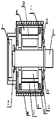
[0009] Such as figure 1 As shown, a transmission shaft structure, which includes a transmission housing 11 and a motor 1 located in the transmission housing 11, a shaft 3 is provided on one side of the motor 1, and the motor 1 is a variable speed adjustable motor. One end of the shaft body 3 is provided with a speed sensor 2, and the inner side of the transmission shell 11 is provided with a transmission inner shell 9, and one side of the transmission inner shell 9 is provided with a first stator core 6, and the first stator core 6 is provided with a stator winding 7, one side of the first stator core 6 is provided with a permanent magnet 5, and the other side of the permanent magnet 5 is provided with a second stator core 10, and the second stator core 10 A limit block 4 is provided on one side, a bearing 8 is provided on the shaft body 3 , and at lea...


PUM


Abstract

The invention discloses a transmission shaft body structure, which comprises a transmission housing (11) and a motor (1) arranged in the transmission housing (11), a shaft body (3) is arranged on one side of the motor (1), and the The motor (1) is a variable speed adjustable motor, a speed sensor (2) is provided at one end of the shaft body (3), a transmission inner case (9) is provided inside the transmission shell (11), and the transmission inner case (9) A first stator core (6) is provided on one side, and a stator winding (7) is provided on the first stator core (6), and one side of the first stator core (6) A permanent magnet (5) is provided, a second stator core (10) is provided on the other side of the permanent magnet (5), and a limit block (4) is provided on one side of the second stator core (10), so A bearing (8) is provided on the shaft body (3), and at least one temperature sensor (12) is provided in the transmission inner shell (9). The invention has the advantages of reasonable structural design and energy saving.

Description

technical field [0001] The invention relates to the technical field of transmission, in particular to the structure of a transmission shaft. Background technique [0002] The structure design of the existing transmission shaft body is unreasonable, the frequency conversion speed regulation cannot be performed, the work efficiency is low, and it is not suitable for industrialized mass production. Contents of the invention [0003] The problem to be solved by the present invention is to provide a drive shaft structure with reasonable structural design. [0004] In order to solve the above problems, the present invention provides a transmission shaft structure, which includes a transmission housing and a motor arranged in the transmission housing, a shaft body is provided on one side of the motor, and the motor is a variable-speed adjustable motor. A speed sensor is provided at one end of the shaft body, a transmission inner casing is provided inside the transmission casing,...

Claims


Application Information

Patent Timeline
IPC IPC(8): H02K7/08H02K11/21H02K11/25
CPCH02K7/08
Inventor 高荣江
Owner 高荣江
Why Eureka
Try Eureka