An anti-interference crystal oscillator installation structure and installation method

A technology of installation structure and installation method, applied in the direction of impedance network, electrical components, etc., can solve the problems of cost increase, board layer increase, space waste, etc., and achieve the effects of reducing interference, ensuring cleanliness, and ensuring reliable fixation

Active Publication Date: 2021-05-25
ZHENGZHOU YUNHAI INFORMATION TECH CO LTD
View PDF13 Cites 0 Cited by
  • Summary
  • Abstract
  • Description
  • Claims
  • Application Information

AI Technical Summary

Problems solved by technology

[0005] However, the current electronic products such as servers have more and more functions, and the layout and wiring density are getting higher and higher. If the wiring design cannot be carried out on several layers under the crystal oscillator, this will cause a waste of space and increase the difficulty of the design, which may lead to The increase of the board layer, which in turn causes the increase of the cost

Method used


Image

  • An anti-interference crystal oscillator installation structure and installation method
  • An anti-interference crystal oscillator installation structure and installation method
  • An anti-interference crystal oscillator installation structure and installation method

Examples


Embodiment Construction

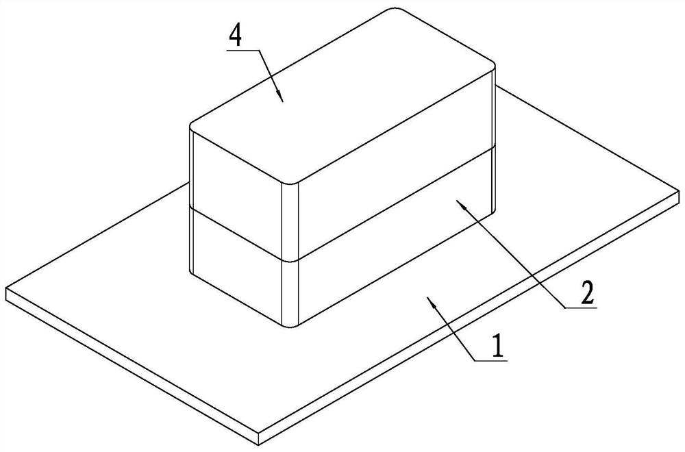
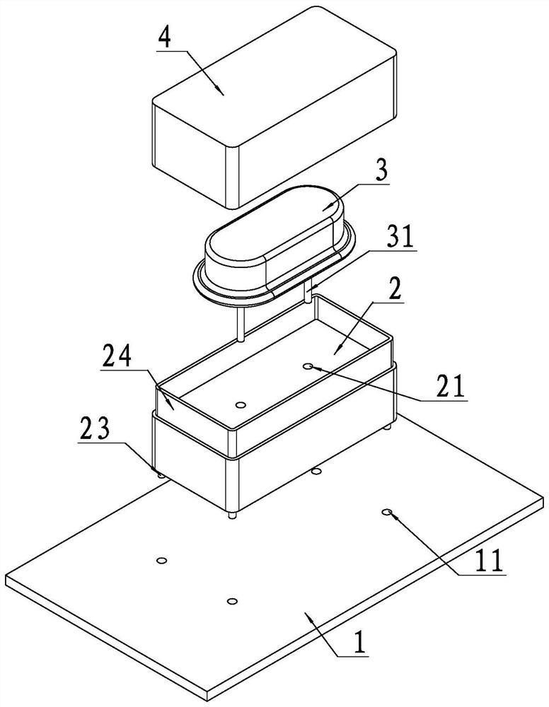
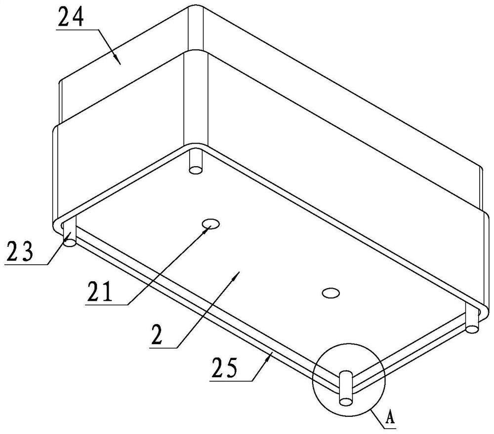
[0037] In order to clearly illustrate the technical features of the present solution, the present invention will be described in detail below through specific implementation methods and in conjunction with the accompanying drawings. The following disclosure provides many different embodiments or examples for implementing different structures of the present invention. To simplify the disclosure of the present invention, components and arrangements of specific examples are described below. Furthermore, the present invention may repeat reference numerals and / or letters in different instances. This repetition is for the purpose of simplicity and clarity and does not in itself indicate a relationship between the various embodiments and / or arrangements discussed. It should be noted that components illustrated in the figures are not necessarily drawn to scale. Descriptions of well-known components and processing techniques and processes are omitted herein to avoid unnecessarily lim...


PUM


Abstract

The invention discloses an anti-interference crystal vibration installation structure and an installation method. The installation structure includes a mounting seat including a mounting seat fixed on a PCB board, the mounting seat is made of metal material, and the mounting seat is A straight-leg type crystal oscillator is provided, and the PIN pin of the straight-leg type crystal oscillator passes through the PIN pin socket of the mounting base against the PCB board, and is fixedly connected to the PCB board, and the PIN pin An insulating layer is arranged between the jack and the PIN pin. By setting the mounting base between the crystal oscillator and the PCB board, the signal of the crystal oscillator is shielded, so as to avoid interference with the signal under the crystal oscillator, so that there is no need to set a clearance area under the crystal oscillator, which simplifies the wiring and can adapt to high density. wiring requirements.

Description

technical field [0001] The invention relates to the technical field of computer hardware equipment, in particular to an anti-interference crystal oscillator installation structure and installation method suitable for straight leg crystal oscillators. Background technique [0002] Crystal oscillators currently used in computers are generally divided into two types, namely, Figure 9 SMD type as shown and as Figure 11 Straight leg shown. Among the traditional installation methods, such as Figure 10 As shown, the chip-type crystal oscillator is fixedly connected to the PCB board by soldering the patch on the crystal oscillator. Such as Figure 12 As shown, in the straight pin crystal oscillator, the PIN pin on the crystal oscillator is inserted into the jack on the PCB board, and the PIN pin of the crystal oscillator is fixedly connected to the PCB board by soldering. [0003] Due to the coupling effect of the crystal oscillator signal, the crystal oscillator will have an...

Claims


Application Information

Patent Timeline
Patent Type & Authority Patents(China)
IPC IPC(8): H03H9/05H03H9/10H03H9/19H03H3/02
CPCH03H3/02H03H9/0542H03H9/10H03H9/19
Inventor 王林
Owner ZHENGZHOU YUNHAI INFORMATION TECH CO LTD
Why Eureka
Try Eureka