Liftable oil barrel mechanism for oil immersion of parts

A technology for parts and lifting motors, which is applied in the field of liftable oil barrel mechanisms for parts immersed in oil, which can solve the problems of oil splashing, easy bumping, and affecting the pass rate, so that it is not easy to be damaged, convenient for manual placement, good effect

Inactive Publication Date: 2018-03-16
FOSHAN RUIPUDA OPTOELECTRONICS TECH CO LTD
View PDF0 Cites 1 Cited by
  • Summary
  • Abstract
  • Description
  • Claims
  • Application Information

AI Technical Summary

Problems solved by technology

[0002] Existing hardware and metal products need anti-rust treatment after processing. The general method is to manually apply it with a brush or manually put it into the oil drum, and the oil drum is generally low. In order to save time and work When personnel directly thr

Method used


Image

  • Liftable oil barrel mechanism for oil immersion of parts

Examples


Example Embodiment

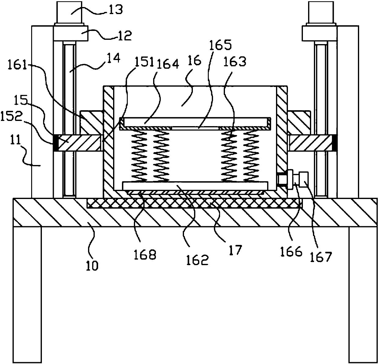
[0014] Example: see figure 1 As shown, a liftable oil drum mechanism for immersing parts in oil includes a frame 10, a vertical main board 11 is fixed on both sides of the top surface of the top plate of the frame 10, and the top surface side wall of the vertical main board 11 is fixed There is a horizontal plate 12, a lifting motor 13 is fixed on the top surface of the horizontal plate 12, the bottom end of the vertical lifting screw 14 is hinged on the top plate of the frame 10, and the top end of the vertical lifting screw 14 is hinged on the horizontal plate 12 to lift The output shaft of the motor 13 is a spline shaft. The spline shaft is inserted into the spline hole on the top of the vertical lifting screw 14. The lifting plate 15 is screwed into the two vertical lifting screws 14. The middle of the lifting plate 15 It has a central through hole 151, the oil barrel 16 is inserted and sleeved in the central through hole 151, the bottom surface of the oil barrel 16 is pres...


PUM


Abstract

The invention discloses a liftable oil drum mechanism for oil immersion of components, which comprises a frame, vertical main boards are fixed on both sides of the top surface of the top plate of the frame, and horizontal plates are fixed on the top side walls of the vertical main board , the lifting motor is fixed on the top surface of the horizontal plate, the bottom end of the vertical lifting screw is hinged on the top plate of the frame, the top end of the vertical lifting screw is hinged on the horizontal plate, the output shaft of the lifting motor is a spline shaft, and the spline shaft The key shaft is inserted into the spline hole at the top of the vertical lifting screw, and the lifting plate is screwed into the two vertical lifting screws. The middle part of the lifting plate has a central through hole, and the oil drum is inserted into the central through hole. The bottom surface of the oil barrel is pressed against the top plate of the frame, the upper outer wall of the oil barrel is fixed with a limit block, and the limit block is pressed against the top surface of the lifting plate; it can lift the oil barrel according to needs, which is convenient for manual placement, and at the same time , the buffer spring it has can ensure that the metal products put in are slowly immersed in the oil, not easy to be damaged, and the effect is good.

Description

Technical field: [0001] The invention relates to the technical field of manufacturing equipment for hardware machinery parts, and more specifically relates to a liftable oil drum mechanism for dipping parts in oil. Background technique: [0002] Existing hardware and metal products need anti-rust treatment after processing. The general method is to manually apply it with a brush or manually put it into the oil drum, and the oil drum is generally low. In order to save time and work When personnel directly throw metal products into the barrel, it is easy to splash the oil, which will affect the environment and generate waste of oil. Moreover, if the metal product is thrown into the oil barrel, it will sink too fast and be easily bumped and damaged, which will affect the pass rate. . Invention content: [0003] The purpose of the present invention is to address the deficiencies of the prior art, and to provide a liftable oil drum mechanism for oil immersion of parts, which c...

Claims


Application Information

Patent Timeline
IPC IPC(8): B05C3/02B05C11/11B05C13/02
CPCB05C3/02B05C11/11B05C13/02
Inventor 叶青
Owner FOSHAN RUIPUDA OPTOELECTRONICS TECH CO LTD
Why Eureka
Try Eureka