
Vehicle distance-measurement anti-collision radar device

An anti-collision radar and vehicle technology, applied in the directions of vehicle parts, transportation and packaging, can solve the problems of inconvenient installation of anti-collision radar, and achieve the effects of simple structure, increased frictional resistance, and easy installation and use.

Pending Publication Date: 2018-03-16
四川嘉义新能有限公司
View PDF6 Cites 1 Cited by
  • Summary
  • Abstract
  • Description
  • Claims
  • Application Information

AI Technical Summary

Problems solved by technology

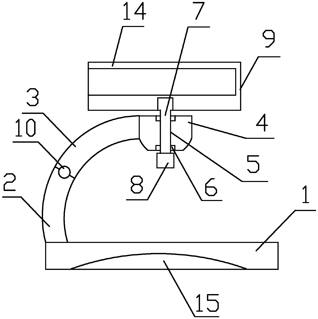
[0003] The technical problem to be solved by the present invention is that the installation of the existing automobile anti-collision radar is inconvenient, and the purpose is to provide vehicle range-finding anti-collision radar equipment, which is a vehicle-mounted portable radar installation structure, simple in structure, easy to install and use, and easy to adjust the angle

Method used


Image

  • Vehicle distance-measurement anti-collision radar device
  • Vehicle distance-measurement anti-collision radar device

Examples


Embodiment 1

[0025] like figure 1 and figure 2 As shown, the present invention provides a vehicle ranging and anti-collision radar device, including a base 1, and also includes a first connecting rod 2, a second connecting rod 3 and a mounting plate 4, and one end of the first connecting rod 2 is axially Fixed on the base 1, the other axial end is connected with the axial end of the second connecting rod 3 through rotation, and the other axial end of the third connecting rod 3 is provided with a mounting plate 4; the mounting plate 4 is provided with Mounting hole 5, described mounting hole 5 is provided with a bearing 6 on the inner wall of axial two ends respectively, also comprises rotating shaft 7, described rotating shaft 7 is arranged in mounting hole 5 through two bearings 6, and the axial end of rotating shaft 7 is provided with There is a rotary knob 8, and the other axial end is connected with the radar box body 9.

Embodiment 2

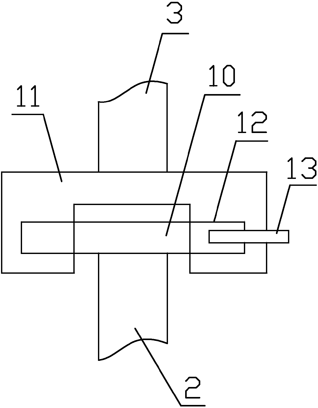
[0027] Further improvement on the basis of Embodiment 1, a fixed shaft 10 is provided on the axial end of the first connecting rod 2 away from the base 1, and the axial direction of the fixed shaft 10 is perpendicular to the axial direction of the first connecting rod 2 The axial end of the second connecting rod 3 away from the mounting plate 4 is provided with a C-shaped connecting block 11, and the inner wall of the C-shaped connecting block 11 is symmetrically provided with two blind holes 12, and the fixed shaft 10 The two ends in the axial direction are installed in two blind holes 12 through bearings for rotation connection; the side wall of the C-shaped connecting block 11 is provided with a through hole, and the axial end surface of the corresponding fixed shaft 10 is provided with a limited hole, through the radial A limit key 13 with a polygonal cross-section passes through the through hole, and is embedded in the limit hole to realize the fixed connection between the...

Embodiment 3

[0029] Further improvement on the basis of Embodiment 2, the upper surface of the mounting plate 4 is provided with a rubber friction pad, and the lower surface of the radar box 9 is in contact with the rubber friction pad.


PUM


Abstract

The invention discloses a vehicle distance-measurement anti-collision radar device. The vehicle distance-measurement anti-collision radar device comprises a base, and also comprises a first connectingrod, a second connecting rod and an installing plate; one end in the axial direction of the first connecting rod is fixed on the base, the other end in the axial direction of the first connecting rodis rotationally connected with one end in the axial direction of the second connecting rod, and the installing plate is arranged at the other end in the axial direction of a third connecting rod; aninstalling hole is formed in the installing plate, and the inner walls of the two ends in the axial direction of the installing hole are each provided with a bearing; the vehicle distance-measurementanti-collision radar device also comprises a rotating shaft, the rotating shaft is arranged in the installing hole through the two bearings, a rotating button is arranged at one end in the axial direction of the rotating shaft, and the other end in the axial direction of the rotating shaft is connected with a radar box. The vehicle distance-measurement anti-collision radar device is a vehicle-mounted portable radar installing structure, the structure is simple, installation and using are convenient, and angle adjustment is also convenient.

Description

technical field [0001] The invention relates to a radar device, in particular to vehicle ranging and anti-collision radar equipment. Background technique [0002] In addition to relying on the driver's driving skills, the safe and reliable driving of a car must also rely on numerous sensor devices to more reliably ensure the safety of drivers and passengers. Millimeter wave radar is one of them. At present, a small number of high-end cars have been installed with on-board millimeter-wave radar when they leave the factory. The millimeter-wave radar is installed on the car and acts as the "eye" of the car, so that the distance, angle and distance between the radar and the measured object can be measured. speed etc. The use of millimeter-wave radar can enable the vehicle to adaptively cruise and follow the vehicle in front; when the car may collide with surrounding objects, the warning device will be used to inform the driver or the vehicle to take automatic emergency braking ...

Claims


Application Information

Patent Timeline
Patent Type & Authority Applications(China)
IPC IPC(8): B60R11/00
CPCB60R11/00B60R2011/0042
Inventor 杨浩
Owner 四川嘉义新能有限公司
Learn More