Exposure mask and exposure method of using the same

An exposure method and mask technology, which are applied in the fields of photomechanical processing of originals, microlithography exposure equipment, photolithography process exposure devices, etc. Effect

Active Publication Date: 2018-03-16
SAMSUNG DISPLAY CO LTD
View PDF5 Cites 0 Cited by
  • Summary
  • Abstract
  • Description
  • Claims
  • Application Information

AI Technical Summary

Problems solved by technology

[0004] Here, as the size of the display device increases, a method of exposing a large substrate by moving a mask smaller than the display device up and down, that is, the stitch exposure (Stitch exposure) method, however, there are Issue where seams are recognized by users as boundaries between said shots

Method used


Image

  • Exposure mask and exposure method of using the same
  • Exposure mask and exposure method of using the same
  • Exposure mask and exposure method of using the same

Examples


Embodiment Construction

[0050] Hereinafter, preferred embodiments of the present invention will be described in more detail with reference to the accompanying drawings.

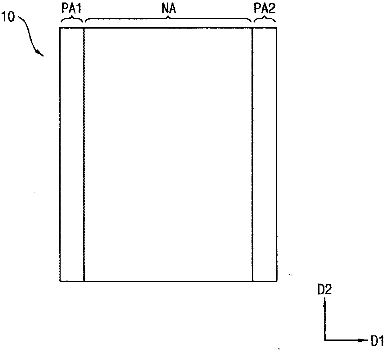
[0051] figure 1 is a plan view of an exposure mask according to an embodiment of the present invention.

[0052] refer to figure 1 , the exposure mask 10 includes: a normal area NA; a first edge position area PA1 adjacent to one side of the normal area NA; It is adjacent to and has a second edge position area PA2 having the same area as the first edge position area PA1. For example, the exposure mask 10 is in the shape of a rectangle, the first edge position area PA1 and the second edge position area PA2 are spaced apart along the first direction D1 and are respectively along a direction substantially perpendicular to the first direction D1. The second direction D2 extends, and the normal area NA may be formed between the first edge location area PA1 and the second edge location area PA2.

[0053] A pattern for forming an exposu...


PUM


Abstract

The invention discloses an exposure mask and an exposure method of using the same. The mask comprises a common region a first edge position region, and a second edge position region. The first edge position region is adjacent to one side of the common region and is divided into multiple units. The second edge position region is adjacent to the other side facing the one side of the common region, is divided into multiple units, and has the same area with the first edge position region. In the common region, patterns used as exposure patterns formed on a substrate of an exposed part are formed on the common region. In the first edge position region, A patterns are formed in the first unit and B patterns are formed in the second unit of the second edge position region in the position corresponding to the first unit. If the A patterns and the B patterns are exposed, exposure patterns which are the same as the exposure patterns of the common region are formed.

Description

technical field [0001] The present invention relates to an exposure mask and an exposure method using the exposure mask, in particular to an exposure method for exposing a mask and a region whose size is larger than the size of the mask. Background technique [0002] Recently, benefiting from the development of technology, display products with smaller size, lighter weight and higher performance are being produced. So far, among display devices, conventional cathode ray tube televisions (cathode ray tube: CRT) have been widely used because of their advantages in performance and price, but they can overcome the disadvantages of CRT in terms of miniaturization and portability. , and display devices with the advantages of miniaturization, light weight and low power consumption, such as plasma display devices, liquid crystal display devices, and organic light-emitting display devices, are attracting attention. [0003] In addition, in the display device, in order to form variou...

Claims


Application Information

Patent Timeline
Patent Type & Authority Applications(China)
IPC IPC(8): G03F1/00G03F7/20
CPCG03F1/00G03F7/70475G03F7/2063G03F7/22G03F7/70466G03F7/2045G03F1/32G03F7/0007G03F7/70775
Inventor 崔容硕朴栽洪姜珉
Owner SAMSUNG DISPLAY CO LTD
Why Eureka
Try Eureka