
Internal environment detecting method of power cabinet

A technology of internal environment and detection method, which is applied in the field of detection, can solve the problems of dangerous accidents of power cabinets, the working environment of power cabinets cannot be monitored in real time, and the monitoring of power cabinets cannot be implemented, so as to achieve the effect of increasing the risk

Inactive Publication Date: 2018-03-16
张静
View PDF0 Cites 3 Cited by
  • Summary
  • Abstract
  • Description
  • Claims
  • Application Information

AI Technical Summary

Problems solved by technology

[0004] The technical problem to be solved by the present invention is that it is impossible to monitor the working environment of the power cabinet, and the power cabinet is prone to dangerous accidents. The purpose is to provide a detection method for the internal environment of the power cabinet and solve the problem that the working environment of the power cabinet cannot be monitored in real time

Method used


Image

  • Internal environment detecting method of power cabinet

Examples


Embodiment 1

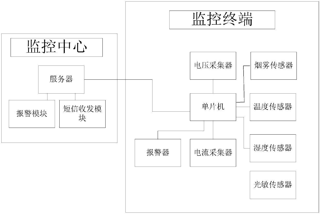
[0026] Such as figure 1 As shown, the internal environment detection method of the power cabinet of the present invention comprises the following steps:

[0027] S1. Establish a monitoring terminal. The monitoring terminal collects data on the temperature and humidity inside the power cabinet. The monitoring terminal monitors whether sparks and smoke are generated inside the power cabinet. The monitoring terminal collects the current and voltage data output by the power cabinet;

[0028] S2. Establish a monitoring center and connect the monitoring terminal with the monitoring center;

[0029] S3. The monitoring center in step S2 obtains the temperature, humidity, current, and voltage data collected by the monitoring terminal in step S1, extracts valid data and compares the data with the corresponding standard value, and judges that the environment inside the power cabinet is abnormal , if there is an abnormal situation, the monitoring center will send out an alarm signal and ...

Embodiment 2

[0034] Based on embodiment 1, the monitoring terminal includes a single-chip microcomputer, a temperature sensor, a humidity sensor, a photosensitive sensor, a smoke sensor, a current collector, a voltage collector, an alarm, a temperature sensor, a humidity sensor, a photosensitive sensor, a smoke sensor, and a current collector , voltage collector, and alarm are all connected to the single-chip microcomputer, the current collector and the voltage collector are connected to the output end of the current and voltage of the power cabinet, and the single-chip microcomputer, temperature sensor, humidity sensor, photosensitive sensor, and smoke sensor are all installed inside the power cabinet; The monitoring center includes a server, a short message transceiver module, and an alarm module, and the short message transceiver module and the alarm module are all connected to the server; the single-chip microcomputer is connected to the server through the communication module.

[0035]...


PUM


Abstract

The invention discloses a method for detecting the internal environment of a power cabinet, comprising the following steps: establishing a monitoring terminal, collecting data on the temperature and humidity inside the power cabinet by the monitoring terminal, monitoring whether electric sparks and smoke are generated inside the power cabinet, and monitoring The terminal collects the current and voltage data output by the power cabinet; establishes a monitoring center and connects the monitoring terminal with the monitoring center; the monitoring center obtains the temperature, humidity, current, and voltage data collected by the monitoring terminal, extracts valid data and compares the data The corresponding standard values ​​are compared to determine whether there is an abnormal situation inside the power cabinet. If there is an abnormal situation, the monitoring center will send an alarm signal to the outside and send an emergency notice to the on-site monitoring personnel of the power cabinet; Communication channel of the fire station. The invention solves the problem that the working environment of the power cabinet cannot be monitored in real time.

Description

technical field [0001] The invention relates to a detection method, in particular to an internal environment detection method of a power cabinet. Background technique [0002] With the continuous expansion of the scale of power grid construction, outdoor power cabinets (ring network cabinets, box-type transformers, power distribution cabinets, branch boxes, etc.) have been widely used due to their advantages of small investment, short construction period, and standardized production. [0003] Due to the limited protective effect of the cabinet and the harsh environment, such as wind, rain, sun exposure, accumulated water and snow, etc., the environment changes drastically, which may easily lead to damage to electrical equipment. There are a large number of power components inside the cabinet. , a large amount of heat will be generated inside, therefore, heat dissipation windows must be installed on the side wall of the power cabinet, but only through the heat dissipation win...

Claims


Application Information

Patent Timeline
Patent Type & Authority Applications(China)
IPC IPC(8): G05B19/042
CPCG05B19/0428G05B2219/24024
Inventor 张静
Owner 张静
Learn More