
Pan-tilt holder drift compensation method

A technology of drift compensation and pan/tilt, which is applied in the direction of electric speed/acceleration control, navigation through speed/acceleration measurement, etc. It can solve the problems of limiting the stability of the pan/tilt and the phase lag of the output signal, and automatically solves the line of sight when it arrives The effect of angular drift

Active Publication Date: 2018-03-16
CHANGCHUN INST OF OPTICS FINE MECHANICS & PHYSICS CHINESE ACAD OF SCI
View PDF6 Cites 11 Cited by
  • Summary
  • Abstract
  • Description
  • Claims
  • Application Information

AI Technical Summary

Problems solved by technology

However, in order to ensure the quality of the output signal, filtering and fusion will also bring about a serious phase lag of the output signal
This phase-lag signal limits the gain of the stabilized gimbal's control algorithm used to achieve inertial stabilization, thereby limiting the gimbal's stabilization performance

Method used


Image

  • Pan-tilt holder drift compensation method
  • Pan-tilt holder drift compensation method
  • Pan-tilt holder drift compensation method

Examples


Embodiment Construction

[0040] In order to enable those skilled in the art to better understand the solutions of the present invention, the following will clearly and completely describe the technical solutions in the embodiments of the present invention in conjunction with the drawings in the embodiments of the present invention. Obviously, the described embodiments are only It is an embodiment of a part of the present invention, but not all embodiments. Based on the embodiments of the present invention, all other embodiments obtained by persons of ordinary skill in the art without making creative efforts shall fall within the protection scope of the present invention.

[0041] The terms "first", "second", "third", "fourth", etc. (if any) in the description and claims of the present invention and the above drawings are used to distinguish similar objects, and not necessarily Used to describe a specific sequence or sequence. It is to be understood that the terms so used are interchangeable under app...


PUM


Abstract

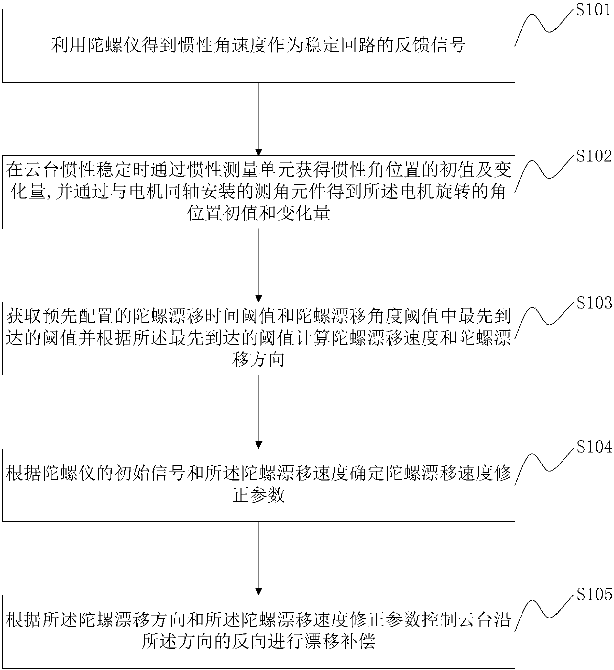
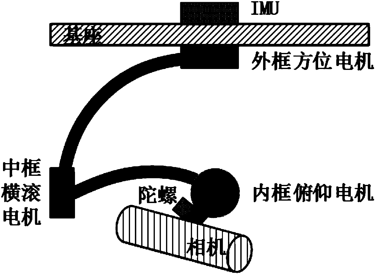
The embodiment of the present invention discloses a pan-tilt holder drift compensation method. The compensation method of the invention is a compensation algorithm which integrates the advantages of agyro and an IMU (Inertial Measurement Unit) adopting filtering and fusion, can realize high-performance inertial stability and automatically solve the problem of line-of-sight angle shift in real time, enables the line-of-sight angle of an imaging device mounted on a pan-tilt holder to steadily and continuously point to a key area so as to realize long-time photographing.

Description

technical field [0001] The invention relates to the technical field of stable imaging of a moving base, in particular to a compensation method for pan-tilt drift. Background technique [0002] In recent years, various types of moving base imaging gimbals have been widely used in aerial photography, unmanned vehicles, robots and other fields, especially the use of unmanned aerial vehicles for aerial photography, which can quickly, flexibly, clearly and accurately obtain photos and video information. The stabilized gimbal is a necessary device for compensating the attitude movement and vibration of the drone and other carriers to ensure that the imaging equipment mounted on the gimbal can achieve clear and stable shooting. [0003] The core component of a stabilized gimbal is an inertial sensor, and common inertial devices include a gyroscope and an inertial measurement unit (IMU, Inertial Measurement Unit). First of all, when simply relying on the gyro to measure the angula...

Claims


Application Information

Patent Timeline
Patent Type & Authority Applications(China)
IPC IPC(8): G05D13/62G01C21/18
CPCG01C21/18G05D13/62
Inventor 田大鹏王中石王福超
Owner CHANGCHUN INST OF OPTICS FINE MECHANICS & PHYSICS CHINESE ACAD OF SCI
Learn More