Permanent-magnet transmission mechanism for stirring device

A technology of permanent magnet transmission and stirring equipment, which is applied to mixer accessories, mixers with rotating stirring devices, permanent magnet clutches/brakes, etc., to achieve effective buffering and shock absorption, improve practicability, and improve overall stability.

Pending Publication Date: 2018-03-16
丁锋燕
View PDF0 Cites 1 Cited by
  • Summary
  • Abstract
  • Description
  • Claims
  • Application Information

AI Technical Summary

Problems solved by technology

[0004] The purpose of the present invention is to provide a permanent magnet transmission mechanism for stirring equipment, which has the advantages of automatic heat dissipation and automatic stable control of the rotational speed, and solves the problem that the permanent magnet transmission mechanism can automatically dissipate heat and stabilize the automatic control of the rotational speed

Method used


Image

  • Permanent-magnet transmission mechanism for stirring device
  • Permanent-magnet transmission mechanism for stirring device
  • Permanent-magnet transmission mechanism for stirring device

Examples


Embodiment Construction

[0022] The following will clearly and completely describe the technical solutions in the embodiments of the present invention with reference to the accompanying drawings in the embodiments of the present invention. Obviously, the described embodiments are only some, not all, embodiments of the present invention. Based on the embodiments of the present invention, all other embodiments obtained by persons of ordinary skill in the art without making creative efforts belong to the protection scope of the present invention.

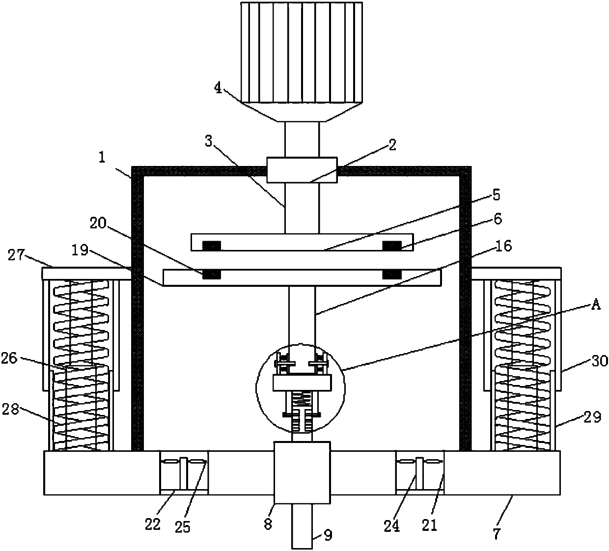
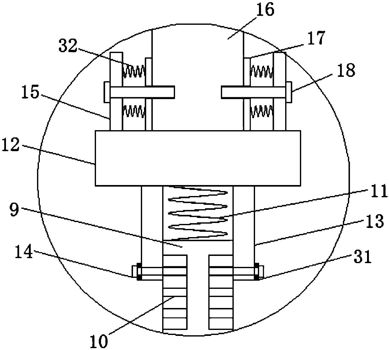
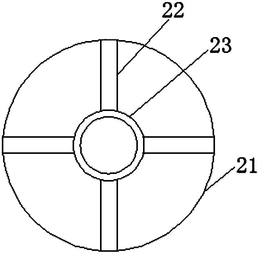
[0023] see Figure 1-3 , the present invention provides a technical solution: a permanent magnet transmission mechanism for stirring equipment, including a housing (1) and a fixing seat (7), the top of the inner side of the housing (1) is connected with a bearing seat (2), The inner side of the bearing seat (2) is provided with a motor shaft (3), the bottom of the motor shaft (3) runs through the bearing seat (2) and extends to the inner side of the housing (1...


PUM


Abstract

The invention discloses a permanent-magnet transmission mechanism for a stirring device. The permanent-magnet transmission mechanism comprises a housing and a fixed base. A driving plate is connectedto the bottom of a motor shaft; and driving permanent magnet blocks are arranged at the two sides of the bottom at the inner side of the driving plate. A connection base is connected to the top of a damping spring. A fixed sleeve is connected to the bottom of the connection base; a first connection sleeve is connected to the top of the connection base; and ventilating slots are formed in the two sides inside the fixed base. A rotation blade is connected to the top of the outer side of a rotation rod. Electric push rods are connected to the two sides of the top of the fixed base; fixed plates are connected to the two sides of the housing; the tops of the electric push rods are connected with the bottoms of the fixed plates; and compression springs sleeve the outer sides of the electric pushrods. The permanent-magnet transmission mechanism has advantages of automatic heat dissipation and automatic and stable rotational speed controlling; and thus the permanent-magnet transmission mechanism is able to realize automatic cooling and automatic and stable rotation speed controlling.

Description

technical field [0001] The invention relates to the technical field of permanent magnet transmission, in particular to a permanent magnet transmission mechanism for stirring equipment. Background technique [0002] The permanent magnet transmission technology uses magnetic force to drive the load to achieve non-contact torque transmission between the motor and the load. The active rotor driven by the motor rotates at high speed, cutting the magnetic field lines in the magnetic field generated by the driven rotor, thereby generating an induced magnetic field. Through the magnetic field The interaction force between them drives the load to work and realizes the transmission of torque. [0003] At present, when the permanent magnet transmission technology is used to drive the stirring shaft in the stirring equipment to rotate, the function of the permanent magnet transmission mechanism is relatively simple, but it can simply stir the stirring equipment. The permanent magnet tra...

Claims


Application Information

Patent Timeline
Patent Type & Authority Applications(China)
IPC IPC(8): H02K49/10H02K9/04B01F7/26B01F13/08B01F15/00B01F15/06B01F27/93
CPCH02K9/04H02K49/108B01F27/93B01F33/453B01F35/221422B01F35/42B01F35/51B01F2035/98B01F35/92
Inventor 丁锋燕
Owner 丁锋燕
Why Eureka
Try Eureka