
Aquiculture underwater monitoring structure applied among a plurality of groups of adjacent net cages

An aquaculture and adjacent technology, applied in the field of aquaculture equipment and monitoring equipment, can solve the problems of simultaneous monitoring, lack of, and difficult aquatic products, and achieves the effects of good practical performance, simple structure, good stability and regulation.

Active Publication Date: 2018-03-16
宿州速果信息科技有限公司
View PDF8 Cites 2 Cited by
  • Summary
  • Abstract
  • Description
  • Claims
  • Application Information

AI Technical Summary

Problems solved by technology

[0004] Looking at the structure of the above-mentioned patents and common water monitoring equipment on the market, it is found that most of these devices are single-camera devices, which do not have a floating structure on the surface of the water body. During aquaculture, most of the breeding bases use adjacent circular cages. For farming, and there is a certain distance between these cages, which are separate cultured bodies, it is difficult to monitor the aquatic organisms in these cages at the same time with only one camera, so it is necessary to design a floating system with water, It has a surrounding structure and is equipped with a water support device with multiple cameras, so as to realize the simultaneous monitoring of aquatic products in adjacent cages
[0005] In order to solve the above-mentioned technical problems, the present invention provides an underwater monitoring structure applied to aquaculture between multiple groups of adjacent net cages, to solve the problem of using net cages for aquaculture, there is a certain distance between the net cages, and they They are all separate cultured bodies, and it is difficult to monitor the aquatic organisms in these cages at the same time with only one camera

Method used


Image

  • Aquiculture underwater monitoring structure applied among a plurality of groups of adjacent net cages
  • Aquiculture underwater monitoring structure applied among a plurality of groups of adjacent net cages
  • Aquiculture underwater monitoring structure applied among a plurality of groups of adjacent net cages

Examples


Embodiment

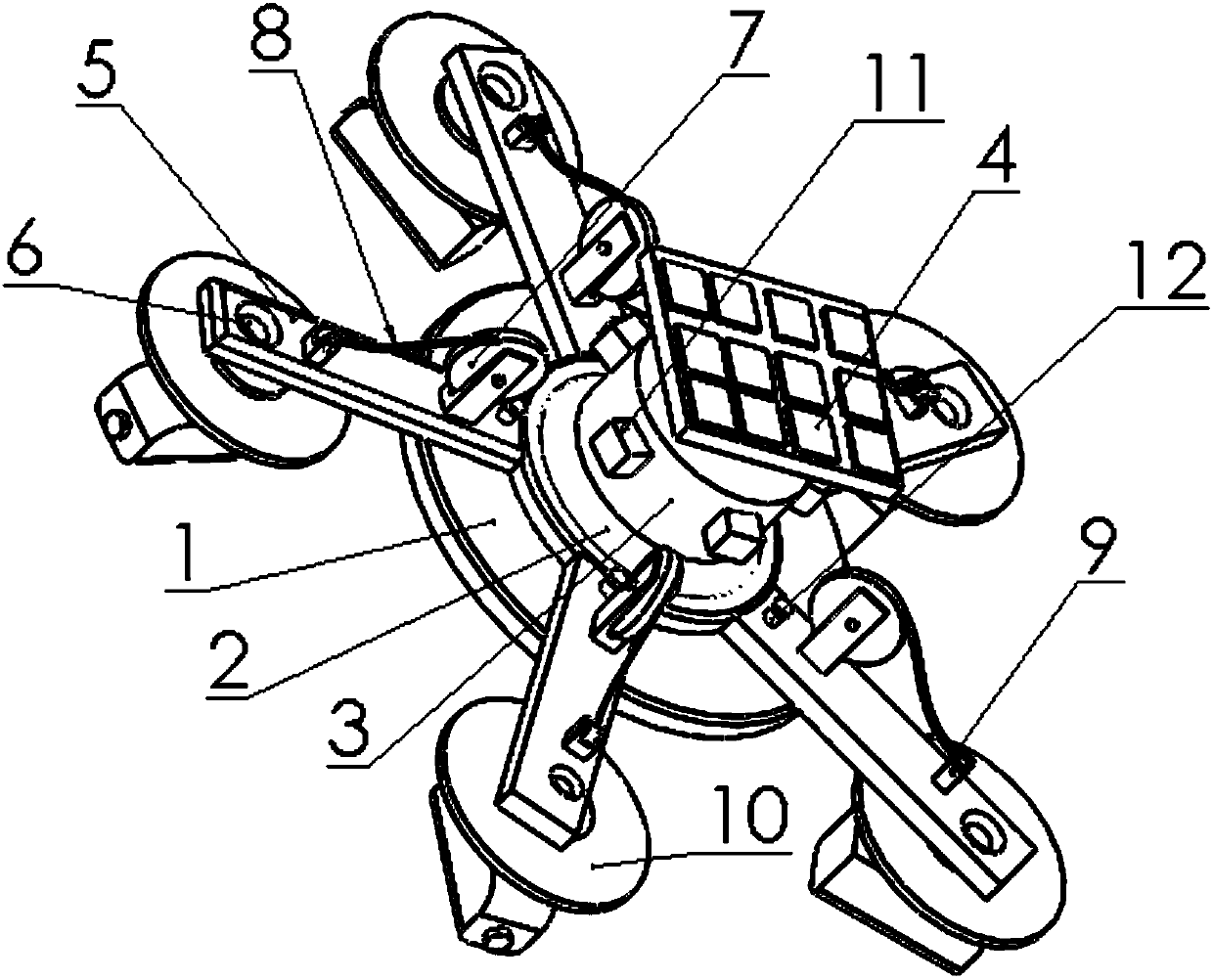
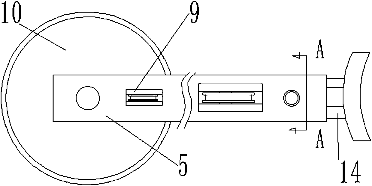
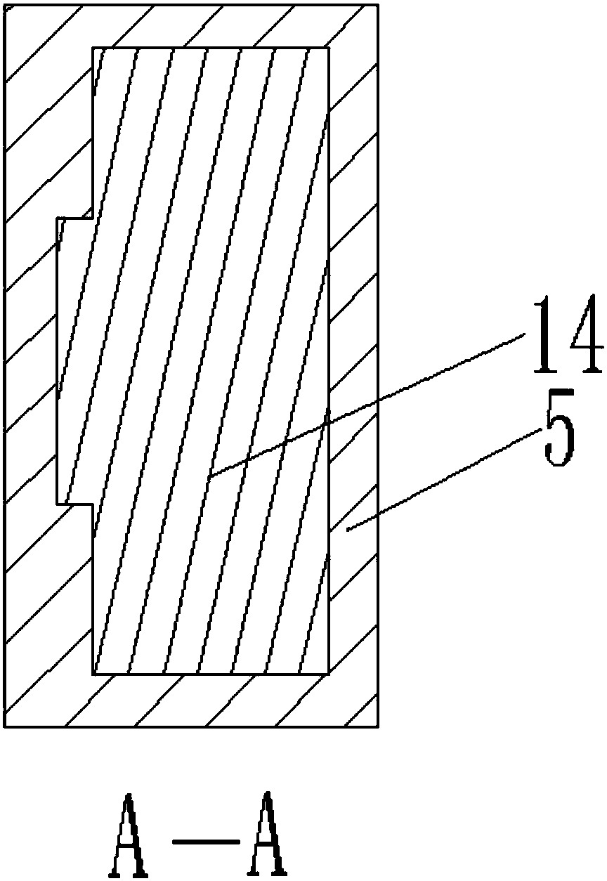
[0029] as attached figure 1 to attach Figure 8 Shown:

[0030] The invention provides an underwater monitoring structure applied to aquaculture between multiple groups of adjacent net cages, including a base floating body 1, a base 2, an electrical box 3, a solar panel 4, a casing 5, a wiring hole 6, and a winding wheel 7. Inlet pipe 8, guide wheel 9, branch floating body 10, junction box 11, locking bolt 12, roller 13, support rod 14, camera 15, large air bag ring 16 and small air bag ring 17, the outer periphery of the base 2 A base floating body 1 is installed, and an electrical box 3 is installed on the top surface of the base 2; a small solar panel 4 is installed on the top surface of the electrical box 3 utilizing a support frame; The supporting rod 14 is set with five casings 5, and a locking bolt 12 with a locking effect runs through between the casing 5 and the supporting rod 14; Five junction boxes 11 are installed, and the junction box 11 is electrically connect...


PUM


Abstract

The invention provides an aquiculture underwater monitoring structure applied among a plurality of groups of adjacent net cages. The underwater monitoring structure comprises wire inlet pipes, branchfloating bodies, junction boxes, locking bolts, rollers, supporting rods, cameras, a big air bag ring and small air bag rings. A base floating body is mounted at the periphery of a base. An electric appliance box is mounted on the top of the base. Small solar panels are mounted on the top of the electric appliance box through utilization of a supporting frame. Five bushings are sleeved at the periphery of the base through utilization of five supporting rods. Small floating body structures also play a role in buoyancy support. The device can float on the surface of a water body relatively stably. Ends of the small floating body structures are directly electrically connected with five cameras through rope pipes, so the five cameras hang down five adjacent aquaculture net cages, and aquatic organisms in the five adjacent net cages can be monitored at the same time. The underwater monitoring structure is simple in structure and is a radial star-shaped structure, has relatively high stability and adjustability and is mainly applied to synchronous monitoring of the net cages in net cage aquaculture.

Description

technical field [0001] The invention belongs to the technical field of monitoring equipment and aquatic equipment, and in particular relates to an underwater monitoring structure applied to aquaculture between multiple groups of adjacent net cages. Background technique [0002] Such as: Application No. 201520090546.0 provides a kind of underwater monitoring equipment, including underwater camera and a fixing device for fixing the underwater camera, the fixing device includes a mounting plate, a slide bar fixed on the mounting plate, and a slide bar that slides The camera bracket and the driving mechanism used to drive the camera bracket are shifted and matched. The sliding bar is provided with a limiting part for limiting the camera bracket; the driving mechanism includes a base set on the top of the sliding bar and a remote control winch fixed on the base. , the camera bracket is fixedly connected with the twisted rope on the remote control winch. [0003] Another example:...

Claims


Application Information

Patent Timeline
Patent Type & Authority Applications(China)
IPC IPC(8): H04N7/18A01K61/60
CPCA01K61/60H04N7/181Y02A40/81Y02P60/60
Inventor 江林伟潘胜民岳宇靖唐豪杰龚宇
Owner 宿州速果信息科技有限公司
Learn More