Supercharge Your Innovation With Domain-Expert AI Agents!

Steering column with electromechanical fixing device

A technology for steering column and fixing equipment, applied in mechanical equipment, fixing device, steering mechanism, etc., can solve the problems of high related cost and large number of components, and achieve the effect of prolonging the closing time

Active Publication Date: 2020-08-18
THYSSENKRUPP PRESTA AG +1
View PDF15 Cites 0 Cited by
  • Summary
  • Abstract
  • Description
  • Claims
  • Application Information

AI Technical Summary

Problems solved by technology

Here, the disadvantage is the high number of components and the associated costs

Method used


Image

  • Steering column with electromechanical fixing device
  • Steering column with electromechanical fixing device
  • Steering column with electromechanical fixing device

Examples


Embodiment Construction

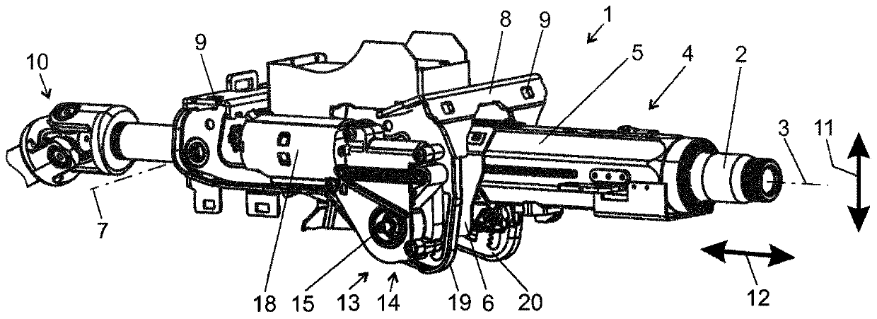
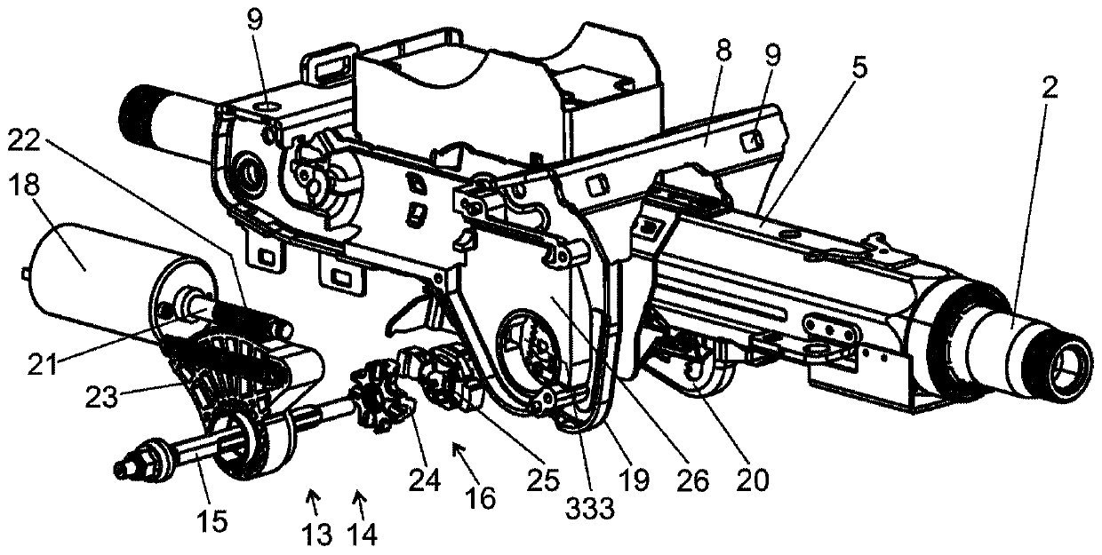
[0041] figure 1 A steering column 1 is shown comprising a steering shaft 2 which is supported in a steering shaft bearing unit 4 by means of a bushing 5 so as to be rotatable about its axis of rotation 3 . The bushing 5 is guided displaceably along the longitudinal axis of the steering shaft 2 in a guide clip 6 . The guide clip 6 is supported pivotably about a pivot axis 7 in a bracket or holding part 8 (in general terms). The holding part 8 can be fastened to the bodywork (not shown) of the motor vehicle at fastening points 9 . The rotational movement introduced into the steering shaft 2 by the driver via a steering wheel (not shown) is introduced into a steering gear (not shown) via a universal joint 10 and other steering shaft components. To increase driver comfort, the steering column 1 can be adjusted in height in a first adjustment direction (also referred to as vertical direction 11 ) and in length in a second adjustment direction (also referred to as longitudinal direc...


PUM


Abstract

The invention relates to a steering column (1) for a motor vehicle which can be adjusted at least in its longitudinal direction (12) and which comprises an outer steering column (5) supporting a steering shaft in a rotational manner (2); holding part (8), which can be connected to the body of the motor vehicle and has two side walls (19, 20), between which the outer steering column (5) is arranged; and electromechanical fixing device (13), in the release position of the electromechanical fixing device, the outer steering column (5) can be adjusted relative to the holding part (8) at least in the longitudinal direction (12) of the steering column (1), and in the electromechanical fixing device The fixed position of the outer steering column (5) is fixed relative to the set position of the holding part (8), wherein the fixing device (13) includes: a clamping pin (15), which passes through the side of the holding part (8) The walls (19, 20) and rotate around their axis during opening and closing of the fixture (13) by means of an electric motor (18) arranged in the housing (26, 27); the cam mechanism (16) and the support bearing (17 ). The side walls (19, 20) of the holding part (8) and the outer steering column (5) are arranged between the cam mechanism (16) and the support bearing (17), and the cam mechanism (16) has two cam discs (24 , 25), the first cam disc (24) is rotationally fixed to the clamping pin (15), and the second cam disc (25) is axially movable within the clamping pin (26, 27) in the housing (26, 27) 15) is directed on. The housings (26, 27) are mounted in a floating manner on the second cam disc (25).

Description

technical field [0001] The present invention relates to an adjustable steering column for motor vehicles. Background technique [0002] Adjustable steering columns are used to adapt the position of the steering wheel to the driver's seating position and are known in various embodiments. In many motor vehicles, the vertical slope of the steering column and / or the distance between the steering wheel and the driver can be adjusted. After adjusting the steering column, secure it in the desired position. For this purpose, a number of clamping mechanisms are known for steering columns of axially and / or vertically adjustable motor vehicles. Despite the use of a lever element, an electrically actuatable steering column mechanism is required due to the high force still required to lock the clamping mechanism. [0003] French published application FR 2 687 628 A1 discloses a clamping mechanism which can be activated by means of an electric actuation element. The steering column is...

Claims


Application Information

Patent Timeline
Patent Type & Authority Patents(China)
IPC IPC(8): B62D1/184
CPCB62D1/184F16H19/001F16B2200/93B62D1/187F16B1/00
Inventor 西蒙·布莱特勒尔珍-皮尔·施佩希特
Owner THYSSENKRUPP PRESTA AG
Features
  • R&D
  • Intellectual Property
  • Life Sciences
  • Materials
  • Tech Scout
  • Unparalleled Data Quality
  • Higher Quality Content
  • 60% Fewer Hallucinations
Learn More