Crane telescopic arm cylinder pin centring position detection device

A technology of detection device and telescopic arm, which is applied in the direction of cranes, transportation and packaging, load hanging components, etc., can solve problems such as low efficiency, inability to accurately find the neutral position, safety accidents, etc.

Pending Publication Date: 2018-03-20
ANHUI LIUGONG CRANE
View PDF0 Cites 3 Cited by
  • Summary
  • Abstract
  • Description
  • Claims
  • Application Information

AI Technical Summary

Problems solved by technology

[0004] (1) Use the spring force to release the pressure in advance when approaching the seat hole, rely on the spring force to slide against the inner wall of the boom, and pin it in naturally when it reaches the seat hole; but this method is easy to cause large mechanical rigid impact and noise Larger, the cylinder pin is prone to local damage due to frequent rigid impact, which will cause damage to the cylinder pin and cause safety accidents
[0005] (2) Proximity sensors are respectively installed on the inner wall of the telescopic cylinder or the boom section, and the relative position of the two is sensed through the proximity sensor; but in this method, the position information sensed by the proximity sensor when the telescopic cylinder moves is a range Value, through this range of values ​​can only determine the position near the seat hole, can not accurately find the median position, need repeated fine-tuning to find the median position, the above method has the disadvantages of low efficiency and slow speed

Method used


Image

  • Crane telescopic arm cylinder pin centring position detection device
  • Crane telescopic arm cylinder pin centring position detection device
  • Crane telescopic arm cylinder pin centring position detection device

Examples


Embodiment Construction

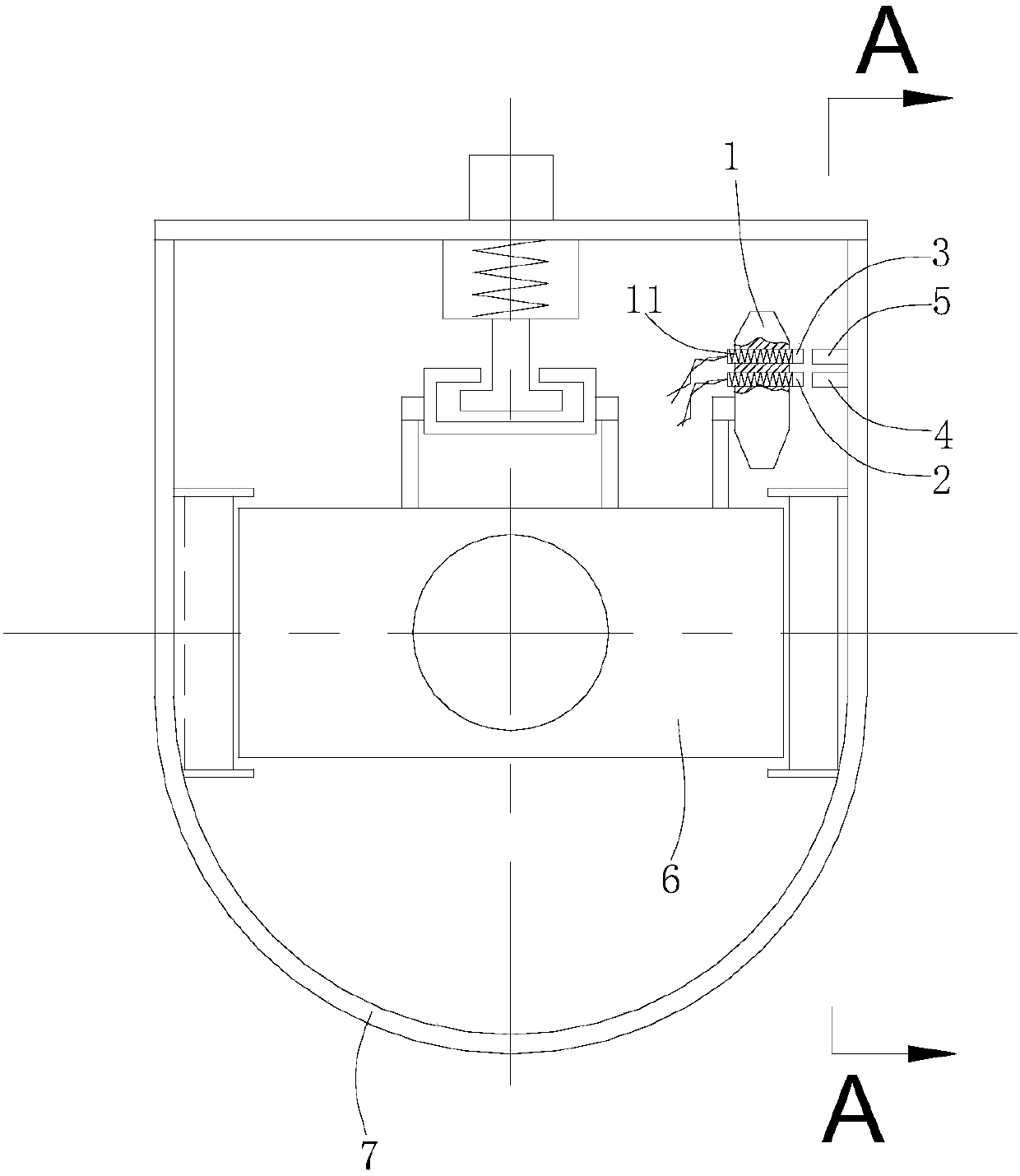
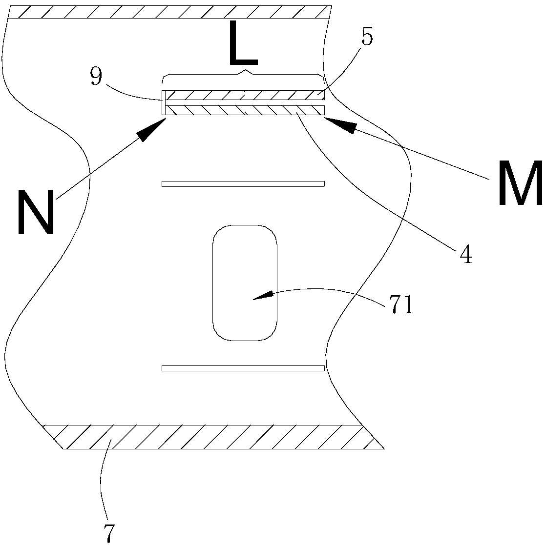
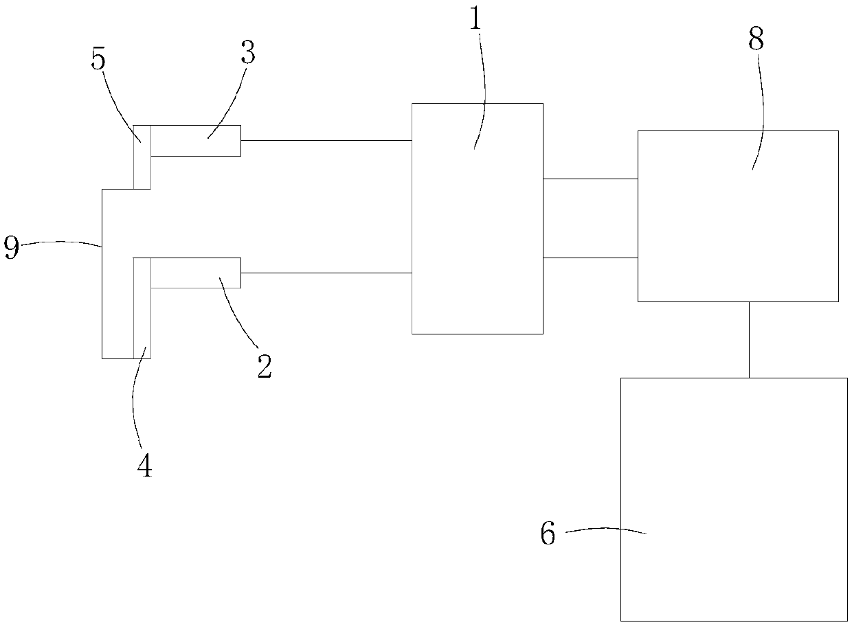
[0019] Such as Figures 1 to 3 shown.

[0020] The detection device includes a detection module 1 , a resistance sliding rail 4 , a conductive block 5 , a first contact piece 2 and a second contact piece 3 .

[0021] The detection module 1 is fixed on the telescopic oil cylinder 6, and the first contact piece 2 and the second contact piece 3 are respectively fixed on the detection module 1 by the reed 11 (that is, the first contact piece 2 and the second contact piece 3 are equivalent to being fixed on the telescopic On the oil cylinder 6), the first contact piece 2 and the second contact piece 3 are respectively aligned with the inner wall of the boom section 7, and the first contact piece 2 and the second contact piece 3 communicate with the detection module 1 through wires respectively.

[0022] The resistance slide rail 4 and the conductive block 5 are fixed on the inner wall of the boom section 7, and the position of the resistance slide rail 4 and the conductive block 5...


PUM


Abstract

The invention provides a crane telescopic arm cylinder pin centring position detection device. The crane telescopic arm cylinder pin centring position detection device comprises a detection module, aresistance sliding rail, a conductive block, a first contact chip and a second contact chip. The first contact chip and the second contact chip are fixed to a telescopic oil cylinder and communicate with the detection module. The resistance sliding rail and the conductive block are fixed to the inner wall of a crane boom section and communicate with each other. The first contact chip makes contactwith the resistance sliding rail when moving along with the telescopic oil cylinder. The second contact chip makes contact with the conductive block when moving along with the telescopic oil cylinder. When the resistance sliding rail makes contact with the first contact chip and the conductive block makes contact with the second contact chip, the first contact chip, the resistance sliding rail, the second contact chip, the conductive block and the detection module form a circuit. The detection module is used for detecting the real-time resistance value of the resistance sliding rail in the circuit. According to the detection device, the resistance sliding rail is used as fixed resistance of a sliding resistor, and resistance changes in the circuit are sent to an external controller to beidentified.

Description

technical field [0001] The invention relates to a device for detecting the center position of a cylinder pin of a telescopic arm of a crane. Background technique [0002] Modern cranes generally use single-cylinder plug-type telescopic cylinders to realize the telescopic function of multi-section booms. On this type of telescopic cylinders, cylinder pins and arm pins are the most critical components for switching connections between booms and transmitting power. The cylinder pin is part of the telescopic cylinder, and the arm pin is part of a boom section. For a certain arm section, the distance between the corresponding cylinder pin seat hole and the arm pin is relatively fixed, which means that on the telescopic cylinder, the cylinder pin and the dovetail groove (this device is used to connect the arm pin to control The disengagement or connection between the two boom sections can be regarded as the relative position of the arm pin seat hole) is also fixed. During the te...

Claims


Application Information

Patent Timeline
Patent Type & Authority Applications(China)
IPC IPC(8): B66C13/16B66C23/693
CPCB66C13/16B66C23/705
Inventor 冯文昌徐青山崔相德朱林徐尚国党伟孙玉魁程伟田善玉
Owner ANHUI LIUGONG CRANE
Why Eureka
Try Eureka