Side intake duct oil-gas separator for engine

A technology of oil and gas separator and side air intake, which is used in engine components, machines/engines, mechanical equipment, etc., can solve the problems of reduced filtration efficiency, filter cotton falling off, loss of filtration function, etc., to achieve high oil and gas separation efficiency, use Good stability and the effect of reducing injection defects

Pending Publication Date: 2018-03-20
宁海县雄达模塑有限公司
View PDF1 Cites 1 Cited by
  • Summary
  • Abstract
  • Description
  • Claims
  • Application Information

AI Technical Summary

Problems solved by technology

It includes a PCV valve cover, a PCV valve base, a main shell, a filter element, a PCV valve diaphragm, a PCV valve spring, an O-ring, and a bracket insert; the PCV valve cover, the PCV valve base, and the main shell are closely connected in sequence Then, the side wall of the PCV valve base is provided with an air outlet, a PCV valve diaphragm is provided between the PCV valve cover and the air outlet of the PCV valve base, and a PCV valve diaphragm is provided between the PCV valve diaphragm and the PCV valve base. PCV valve spring, the side wall of the main housing is provided with a mixed air inlet, and the main housing is provided with a filter element and an oil return port at the lower part. The filter element includes a filter element shell, filter cotton, filter element regulating valve, filter element seat Filter element spring, filter element spring leaf, and filter element lower shell; however, the oil return speed of this structure is slow during use, resulting in the accumulation of lubricating oil in the main casing, resulting in a large overall vibration, which in turn makes the connection of the pipeline and the main casing The connection with the engine is prone to loosening or falling off, and the large vibration will easily cause the filter cotton to fall off and block or lose the filtering function, and the use stability is poor; There must be a gap between the lower end of the shell and the filter element seat, otherwise the lubricating oil under the filter cotton cannot flow to the oil return hole, and the filtered gas will easily enter the mixture inlet from the gap between the lower end of the filter element shell and the filter element seat, resulting in series Gas, the mixed gas is also easy to enter the gap between the lower end of the filter element housing and the filter element seat directly into the filter chamber, resulting in a decrease in filtration efficiency, and the mixed gas also enters the filter element regulating valve from the middle of the filter element seat upwards, so the mixed gas is easy to flow from The oil return hole enters the oil return port and returns to the cylinder body, resulting in low oil and gas separation efficiency

Method used


Image

  • Side intake duct oil-gas separator for engine
  • Side intake duct oil-gas separator for engine
  • Side intake duct oil-gas separator for engine

Examples


Embodiment Construction

[0025] The present invention will be further described below in conjunction with the accompanying drawings and specific embodiments.

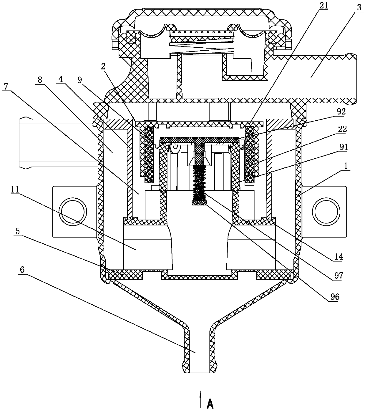
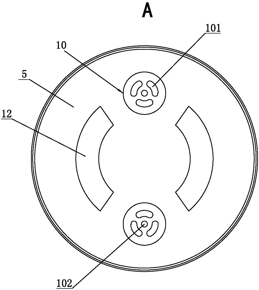
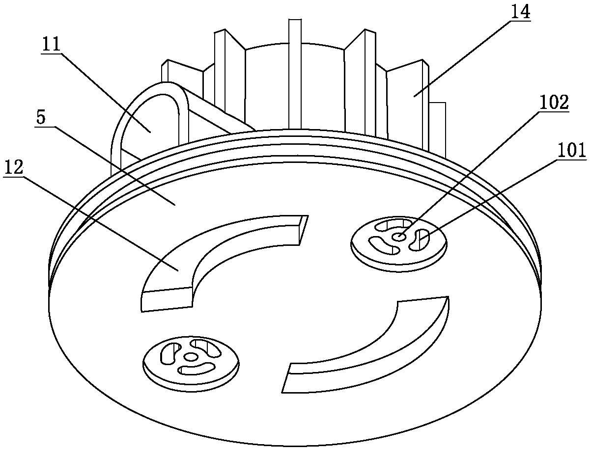
[0026] Such as figure 1 , figure 2 , image 3 , Figure 4 , Figure 5 , Figure 6 , Figure 7 and Figure 8As shown, the present invention provides a kind of engine side intake oil-air separator, and it comprises housing 1 and filter element 2 (also comprises other components of course, but because the invention point that does not relate to the invention of the present invention, so no longer repeat them here ), the housing 1 is divided into upper and lower parts, which is convenient for the injection molding of the housing 1 after being set up in this way, and the upper and lower parts are welded to form the housing 1, and the air inlet is located on the side of the upper end of the housing 1 and communicates with the spiral separation chamber 8 , the shell 1 is provided with an air outlet 3, a separation seat 4, a base 5 and an oil r...


PUM


Abstract

A side intake duct oil-gas separator for an engine comprises a shell body (1) and a filter element (2), an air outlet (3), a separation seat (4), a base (5) and an oil return port (6) are sequentiallyformed in the shell body (1) from top to bottom, the separation seat (4) separates the inner cavity of the shell body (1) into a filter cavity (7) and a spiral separation cavity (8), and the filter cavity (7) is located in the separation seat (4) to communicate with the air outlet (3). The base (5) separates the spiral separation cavity (8) from the oil return port (6), and the lower end face ofthe separation seat (4) abuts against the upper end face of the base (5). An adjusting valve (9) and at least one oil return hole (10) are formed in the base (5), the adjusting valve (9) and the filter element (2) are both located in the separation seat (4), the adjusting valve (9) is located below the filter element (2), and the upper end of the adjusting valve (9) is in the filter element (2). The oil return hole (10) is located in the projection of the separation seat (4) on the base (5), the oil return hole (10) communicates with the filter cavity (7) and the oil return port (6), and a single-way valve is arranged in the oil return hole (10). An air inlet channel (11) for enabling the filter cavity (7) to communicate with the spiral separation cavity (8) is formed in the upper end of the base (5). Compared with the prior art, the side intake duct oil-gas separator has the characteristics of being low in improvement cost, not liable to blow back, high in oil and gas separation efficiency and good in using stability.

Description

technical field [0001] The invention relates to the technical field of engine oil-gas separation, in particular to a side intake oil-gas separator for engines. Background technique [0002] The oil-air separator is connected next to the crankcase ventilation valve of the engine, because when the engine is working, the blow-by gas of the cylinder and the oil vapor will generate pressure, which will cause damage to the engine, so it needs to be vacuumed through the crankcase ventilation valve, because There is a large amount of oil vapor in the gas extracted by the crankcase ventilation valve, so the oil-gas separator mainly separates the oil vapor into oil and steam, so that the oil is collected by the pan and flows back to the engine for reuse, and the steam flows to the engine for re-combustion. Prevent direct entry into the atmosphere and cause air pollution. [0003] The Chinese utility model of the prior art, such as application number 201520630355.9, discloses an oil-g...

Claims


Application Information

Patent Timeline
IPC IPC(8): F01M13/04F01M13/00
CPCF01M13/0011F01M13/0416F01M2013/0438Y02T10/12
Inventor 葛诗健
Owner 宁海县雄达模塑有限公司
Why Eureka
Try Eureka