Layout method of igniters in large-size scramjet

A technology of ramjet and layout method, applied in ramjet engine, engine manufacturing, machine/engine, etc., can solve the problem of inability to apply large-size ramjet combustion, and achieve the effect of increasing thrust and improving utilization rate

Active Publication Date: 2018-03-20
HARBIN INST OF TECH
View PDF3 Cites 0 Cited by
  • Summary
  • Abstract
  • Description
  • Claims
  • Application Information

AI Technical Summary

Problems solved by technology

[0003] The purpose of the present invention is to solve the problem that the existing ignition method can only be ignited close to the engine wall and cannot be applied to the combustion of large-scale ramjet engines, and provides a layout method for igniters in large-size ramjet engines

Method used


Image

  • Layout method of igniters in large-size scramjet
  • Layout method of igniters in large-size scramjet

Examples


specific Embodiment approach 1

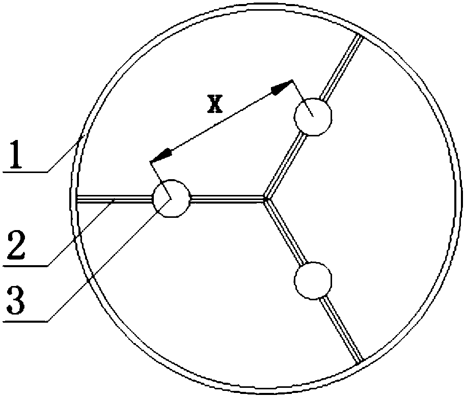
[0010] Specific Embodiment 1: In this embodiment, the layout method of the igniter in a large-scale ramjet engine is as follows: 1. Test the effective ignition diameter of the igniter: carry out the ignition and combustion experiment of a single igniter, and determine the effective ignition of a single igniter by shooting with a high-speed camera The largest diameter D;

[0011] 2. Needle net layout: There are multiple igniters in the combustion chamber of the engine, and the position of the igniters is set according to the congestion ratio of less than 15%; on the cross-section of the engine, the center-to-center distance between two adjacent igniters is (0.7-1.3)D , and the three adjacent igniters are arranged in an equilateral triangle.

[0012] The value of the maximum diameter D in this embodiment is affected by factors such as the type of fuel and the working fluid of the igniter, and the value of D is also different for different types of fuel and working fluid of the i...

specific Embodiment approach 2

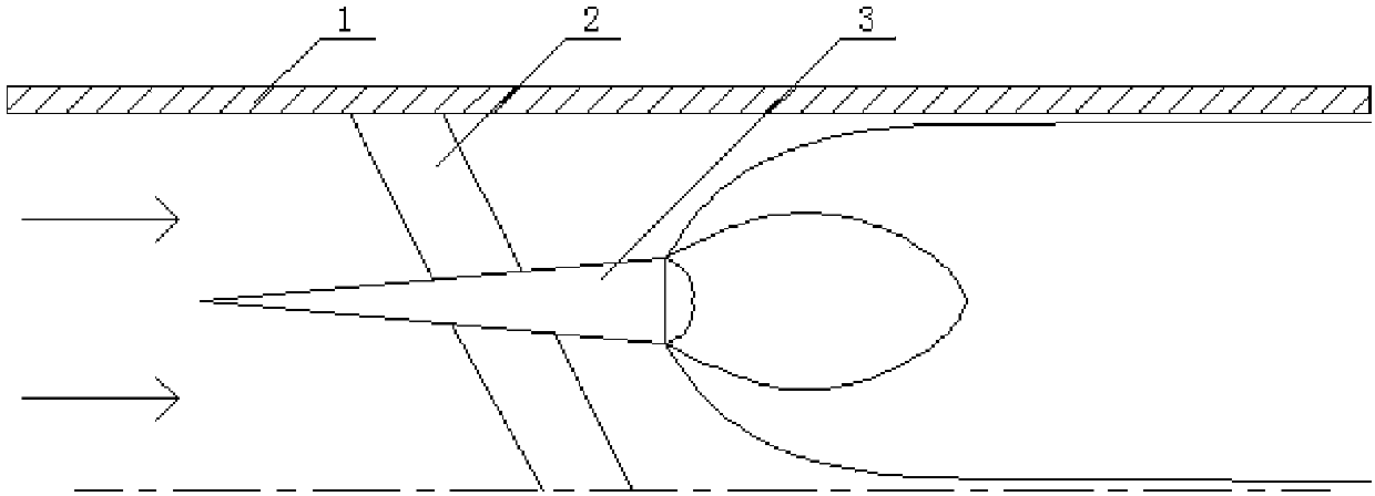
[0014] Embodiment 2: The difference between this embodiment and Embodiment 1 is that the igniter 3 is fixed in the combustion chamber of the engine 1 through the support plate 2; the surface of the igniter 3 is uniformly provided with a plurality of first oil seepage holes; The inside of the support plate 2 is provided with a through hole, one end of the through hole is connected to the oil supply, gas supply and power supply lines on the engine, and the other end is connected to the igniter 3; the surface of the support plate 2 is evenly provided with a plurality of second oil seepage hole, the second oil seepage hole communicates with the through hole inside the support plate 2. Others are the same as the first embodiment.

specific Embodiment approach 3

[0015] Embodiment 3: This embodiment differs from Embodiment 1 or Embodiment 2 in that: the horizontal central axis of the igniter is parallel to the horizontal central axis of the engine. Others are different from the first or second specific embodiment.


PUM


Abstract

The invention discloses a layout method of igniters in a large-size scramjet and aims to solve the problems that ignition can only be conducted close to the wall faces of scramjets through existing ignition methods, and the existing methods cannot be applied to combustion of large-size scramjets. The method comprises the steps that the effective ignition diameters of the igniters are tested; and grid layout is conducted, specifically, the multiple igniters are arranged in a combustion chamber of the scramjet, the positions of the igniters are set with the congestion ratio being lower than 15%,on the cross section of the scramjet, the center-to-center distance between every two adjacent igniters is (0.7-1.3)*D, and every three adjacent igniters are arranged in a regular triangle shape. According to the provided layout method of the igniters in the combustion chamber of the large-size scramjet, by reasonably designing the positions of the igniters, the ignition and combustion efficiencyin the large-size scramjet is improved, and a main flow region is effectively used for air intake. The layout method is applied to the field of scramjets.

Description

technical field [0001] The invention relates to a layout method of an igniter in a large-scale ramjet engine. Background technique [0002] With the improvement of the thrust requirements of the ramjet engine, the intake air volume of the ramjet engine is getting larger and larger, and the geometric size of the engine is also getting bigger and bigger. The existing combustion organization mode of concave cavity combustion can only be ignited and burned close to the wall of the engine. The high-speed mainstream area with the largest air flow cannot be used, and the large heat load brought to the engine wall becomes a factor limiting the increase in engine thrust, which cannot be applied to large-scale ramjet engines. Contents of the invention [0003] The purpose of the present invention is to solve the problem that the existing ignition method can only be ignited close to the engine wall and cannot be applied to the combustion of large-scale ramjet engines, and provides a ...

Claims


Application Information

Patent Timeline
Patent Type & Authority Applications(China)
IPC IPC(8): F02K7/10
CPCF02K7/10F05D2240/35F05D2250/30
Inventor 唐井峰孟繁星李寄于达仁
Owner HARBIN INST OF TECH
Why Eureka
Try Eureka