Circuit of voltage multiplier with programmable output

Inactive Publication Date: 2006-11-23
SITRONIX TECH CORP
View PDF4 Cites 10 Cited by
  • Summary
  • Abstract
  • Description
  • Claims
  • Application Information

AI Technical Summary

Benefits of technology

[0008] Besides, for avoiding the efficiency loss and the life reduction resulted from the pumping CKT too frequently switching, the feedback voltage derived from the output terminal of the pumping CKT can be divided into the first feedback signal and the second feedback signal by a voltage divider circuit. With the help of a multiplexer, the two feedback signals connect to the comparator at

Problems solved by technology

The aforementioned voltage converter, which is dropped by the bandgap 1 and then pumped by the multiple pumping CKT 2 such that the power consumption is quite serious.
However

Method used


Image

  • Circuit of voltage multiplier with programmable output
  • Circuit of voltage multiplier with programmable output
  • Circuit of voltage multiplier with programmable output

Examples


first embodiment

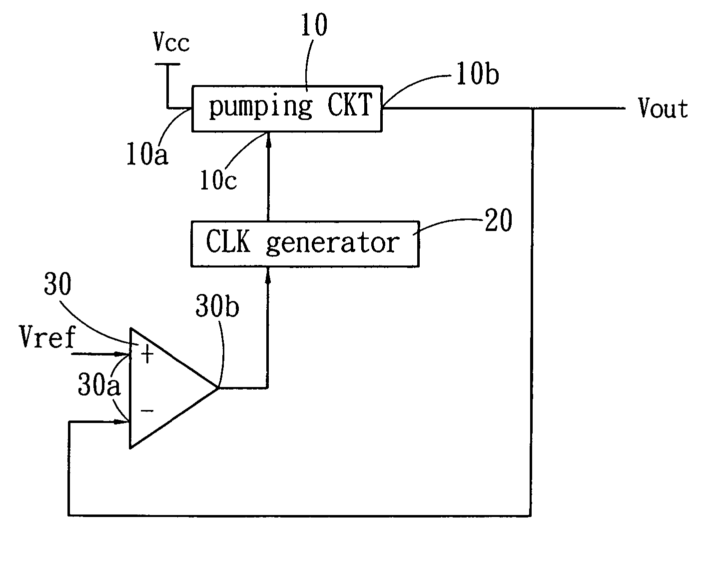
[0017] Please refer to FIG. 3, which is the present invention. The multiple circuit of this invention is composed of a pumping CKT 10, a CLK generator 20, and a comparator 30.

[0018] The pumping CKT 10 has an input terminal 10a, a control terminal 10c, and an output terminal 10b.

[0019] The CLK generator 20 connects to the control terminal 10c of the pumping CKT 10, and the clock signal generated by the CLK generator 20 controls the pumping CKT 10 to start or stop. The pumping CKT 10 pumps the input voltage Vcc at the input terminal 10a of the pumping CKT 10 to be the output voltage Vout at the output terminal 10b of the pumping CKT 10.

[0020] The comparator 30 has two input terminals 30a and one output terminal 30b. The output terminal 30b of the comparator 30 connects to the CLK generator 20. One of the input terminals 30a of the comparator 30 connects to the output terminal 10b of the pumping CKT 10, and the other input terminal 30a of the comparator 30 connects to a reference vol...

second embodiment

[0022] Please refer to FIG. 4, which shows this invention. The multiple circuit of this invention is composed of a pumping CKT 10, a CLK generator 20, a comparator 30, and a voltage divider 50.

[0023] The CLK generator 20 connects to the control terminal 10c of the pumping CKT 10, and the clock signal generated by the CLK generator 20 controls the pumping CKT 10 to start or stop. The pumping CKT 10 pumps the input voltage Vcc at the input terminal 10a of the pumping CKT 10 to be the output voltage Vout at the output terminal 10b of the pumping CKT 10.

[0024] The pumping CKT 10 has an input terminal 10a, a control terminal 10c, and an output terminal 10b.

[0025] The CLK generator 20 connects to the control terminal 10c of the pumping CKT 10, and the discontinuous clock single generated by the CLK generator 20 controls the pumping CKT 10 to start or stop. The pumping CKT 10 pumps the input voltage Vcc at the input terminal 10a of the pumping CKT 10 to be the output voltage Vout at the ...


PUM


Abstract

The circuit of voltage multiplier with programmable output, which compares the feedback voltage of the output with a reference voltage, whether the pumping circuit functions to pump the output voltage or not is controlled by a clock generator so as to sustain the output voltage within a prescribed range, moreover, by using a voltage regulator to supply a stable output voltage to the load.

Description

FIELD OF THE INVENTION [0001] The present invention relates to a circuit of voltage multiplier, especially for a circuit of voltage multiplier with low-power-consumption and programmable output. BACKGROUND OF THE INVENTION [0002] DC power is the most frequently used voltage source for electronic equipments. For the use of electronic equipments with different driving voltages, a DC-DC converter usually will be used to change the magnitude of a voltage. Please refer to FIG. 1, which is a well-known DC-DC voltage converter. It is composed of a bandgap 1, a pumping CKT 2, and a regulator 3. A user can choose the properties of the components according to the required supply voltage. Assume that the user needs a 7.2v output voltage Vout and a 2.4˜3.6 system voltage Vcc, who may choose a 1.2v bandgap 1 and a six-times pumping CKT 2. The system voltage Vcc is first dropped to 1.2v by the bandgap 1, then is pumped to the 7.2v output voltage by the six-times pumping CKT 2, finally is regulate...

Claims


Application Information

Patent Timeline
IPC IPC(8): G05F1/10
CPCH02M2001/0041H02M3/073H02M1/0041
Inventor CHANG, YUCHENGHUANG, CHING-HUO
Owner SITRONIX TECH CORP
Why Eureka
Try Eureka