

Centrifugal compressing apparatus
a centrifugal compressing and centrifugal technology, applied in the direction of liquid fuel engines, marine propulsion, vessel construction, etc., can solve the problem of pressure loss resulting from the main flow direction flow velocity drop, and achieve the effect of restrainting the loss of efficiency and low pressure loss
- Summary
- Abstract
- Description
- Claims
- Application Information
AI Technical Summary
Benefits of technology
Problems solved by technology
Method used
Image

Examples
first embodiment
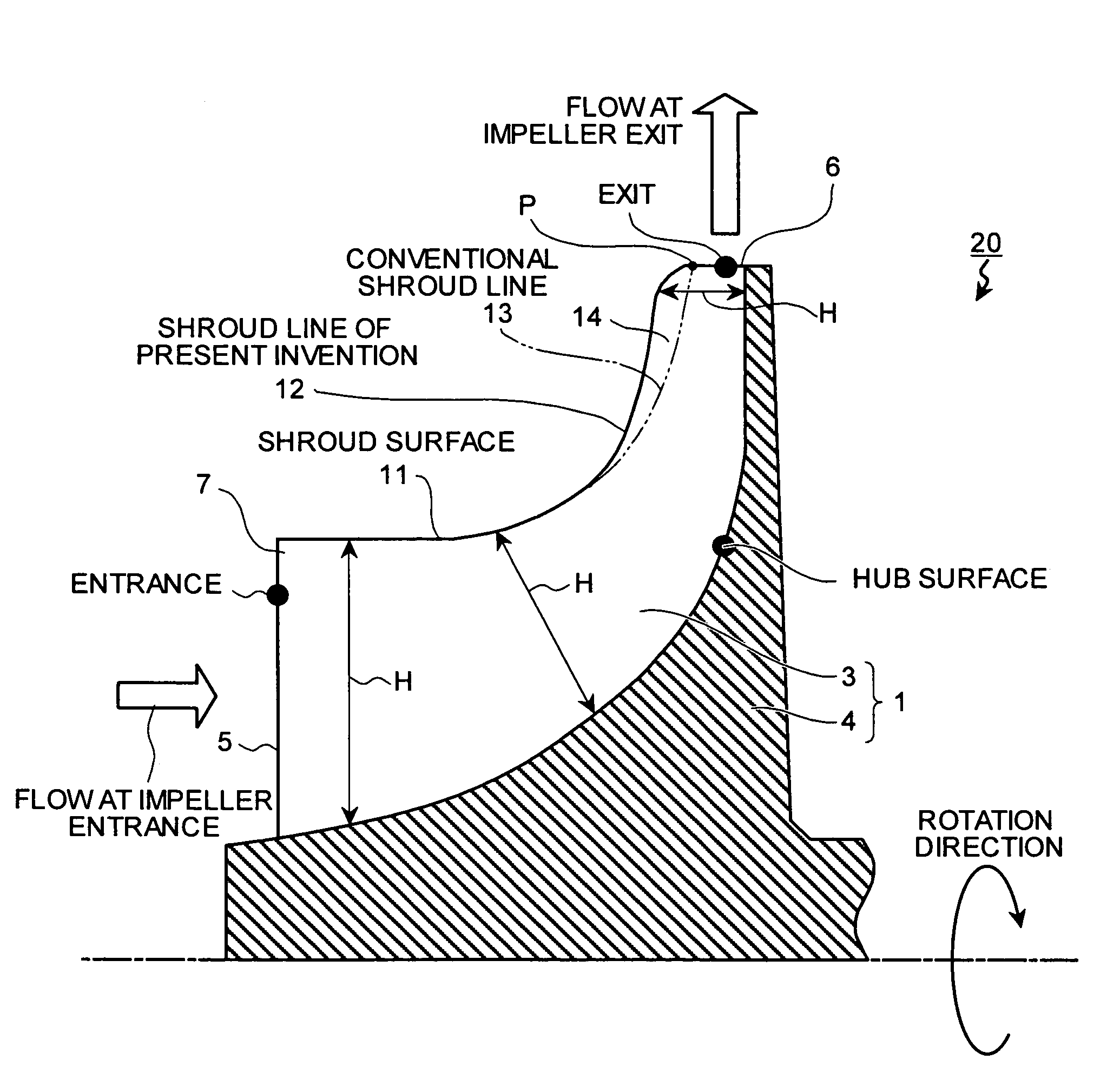
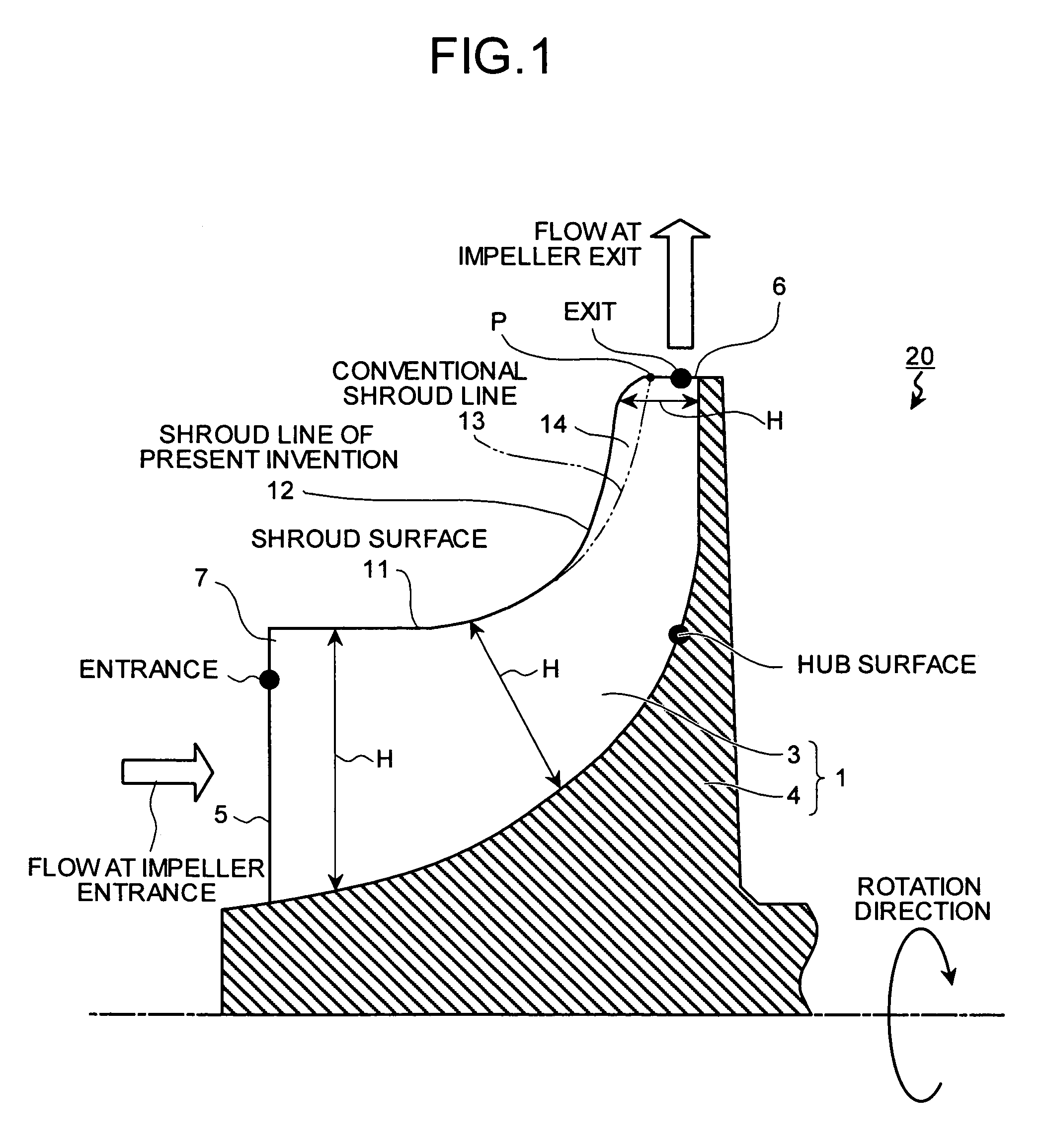
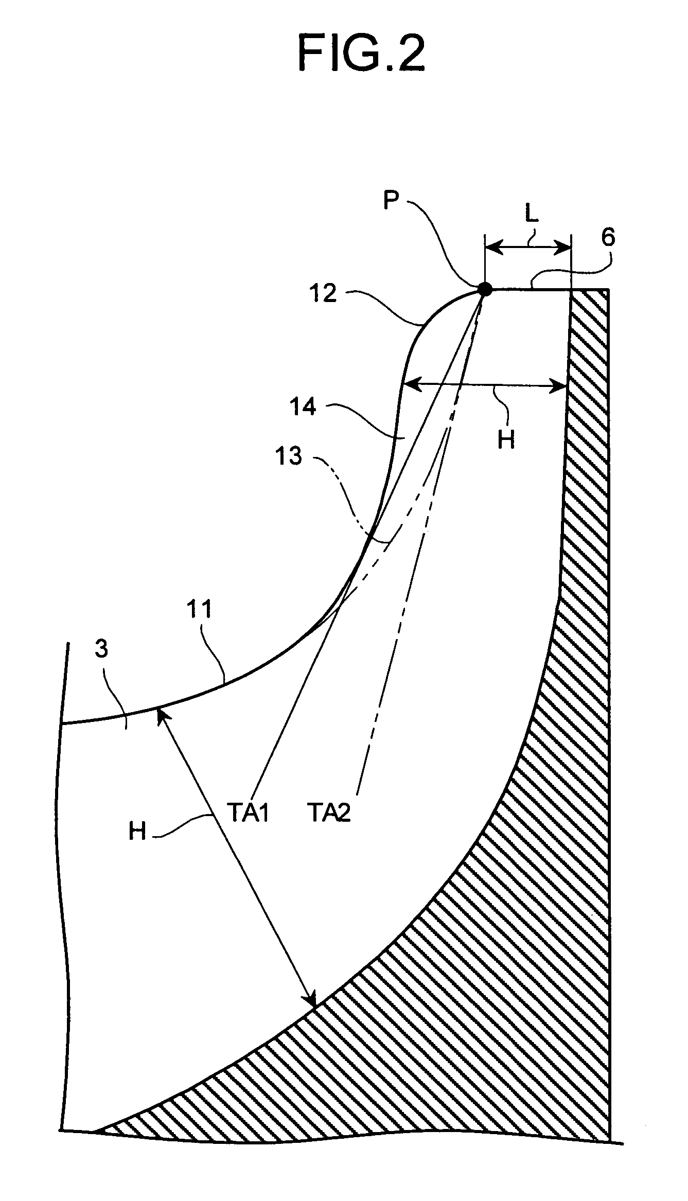
[0033]A first embodiment shall now be described with reference to FIG. 1 and FIG. 2. FIG. 1 is a side view of an impeller 1 of a centrifugal compressing apparatus 20 according to a first embodiment, and FIG. 2 is an enlarged view of the principal portions.
[0034]As shown in FIG. 1, a line (shroud line) 12 of a shroud surface 11 of the blade 3 that opposes a casing (not shown) at a top edge 7 side of the blade 3 is formed so as to bulge in the direction of expanding the height H of the blade 3 in comparison to a shroud line 13 of the conventional centrifugal compressing apparatus 10 of FIG. 7. With the blade 3, the bulged portion (convex portion) is indicated by reference symbol 14. By the blade 3 having the convex portion 14, the height H of the blade 3 is made higher than in the conventional arrangement.
[0035]In FIG. 2, reference symbol TA1 denotes, in the blade 3 of the centrifugal compressing apparatus 20, a tangent that is drawn starting from a point P, located at a distance of a...
second embodiment
[0050]A second embodiment shall now be described with reference to FIG. 5.
[0051]In the second embodiment, description of portions in common to the first embodiment shall be omitted and only the characteristic portions of the second embodiment shall be described.
[0052]As shown in FIG. 5, with a centrifugal compressing apparatus 30 of the second embodiment, a hub line 17, at a base end 16 side that is the side of the blade 3 that is mounted to the hub 4, is formed so as to be depressed in the direction of increasing the height H of the blade 3 in comparison to a hub line 15 of the conventional centrifugal compressing apparatus 10 of FIG. 7. The portion of difference (concave portion) of the blade 3 is denoted by the reference symbol 18. The blade 3 has the convex portion 18 and the height H of the blade 3 is thereby made greater than that in the conventional arrangement. The hub line 17 is the boundary between the base end 16 of the blade 3 of the impeller 1 and the hub 4 onto which t...
third embodiment
[0058]A third embodiment shall now be described with reference to FIG. 6.
[0059]In the third embodiment, description of portions in common to the above-described embodiments shall be omitted and only the characteristic portions of the third embodiment shall be described.
[0060]With a centrifugal compressing apparatus 40 of the third embodiment, the blade 3 has both the convex portion 14 of the first embodiment and the convex portion 18 of the second embodiment. The third embodiment can therefore exhibit the actions and produce the effects of both the first embodiment and the second embodiment.
[0061]As described above, in each of the first to third embodiments, by changing the exit shape of the impeller 1 and thereby making the height H of the blade 3 high at an intermediate portion, the ratio (Δb / H) of the width of the clearance CL and the height H of the blade 3 is made relatively small. As a result, the ratio of the flow path area occupied by the clearance flow CLF to the flow path ...
PUM
 Abstract
Description
Claims
Application Information