Moving plate continuously variable transmission belt

A technology of continuously variable transmission and transmission belt, which is applied in the direction of transmission belts, belts/chains/gears, mechanical equipment, etc., which can solve the problems of poor anti-overload and anti-shock performance, large sliding rate, and low load-carrying capacity, and achieve anti-overload and anti-shock resistance The effect of poor performance, large slip rate, and low load-carrying capacity

Active Publication Date: 2021-01-19
陈学琴
View PDF25 Cites 0 Cited by
  • Summary
  • Abstract
  • Description
  • Claims
  • Application Information

AI Technical Summary

Problems solved by technology

[0003] At present, the transmission belt or chain of continuously variable transmission mostly adopts friction transmission, because of its small transmission torque, low load-carrying capacity, poor anti-overload and anti-impact performance, large slip rate, and low mechanical efficiency; some also have pulsating output and discontinuous power flow. Phenomenon; transmission of power needs to increase the pressure on the transmission belt to increase the friction, thus causing a large power loss, and causing the load of each bearing to increase, and the bearing is easy to be damaged; the effective contact surface for power transmission is small, Theoretically, it is line contact or point contact, and the local stress is large, which may easily lead to scratches or gluing of the working surface, limited transmission power, and short life, which limits the scope of application
The slide chain relies on the groove sprocket and the slide chain to transmit power in a quasi-engagement manner. It has the advantages of low sliding rate, precise transmission, wear resistance, and high impact capacity. However, because the slide of the slide chain is on the slide chain It is a non-continuous arrangement. When the sliders of the slider chain mesh with the grooves on the surface of the grooved sprocket, only one or a few pieces may be stressed, so it is easy to cause the sliders to break and damage

Method used


Image

  • Moving plate continuously variable transmission belt
  • Moving plate continuously variable transmission belt
  • Moving plate continuously variable transmission belt

Examples


Embodiment Construction

[0026] Hereinafter, embodiments of the present invention will be further described with reference to the drawings.

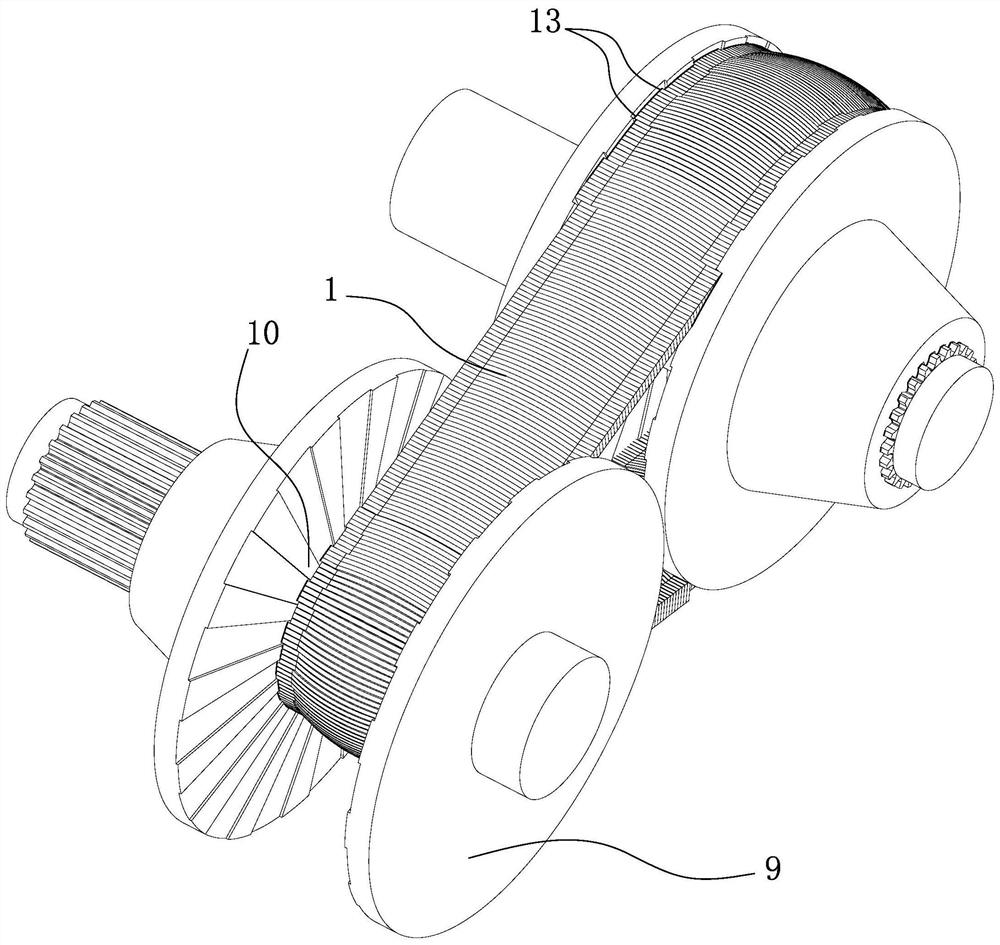
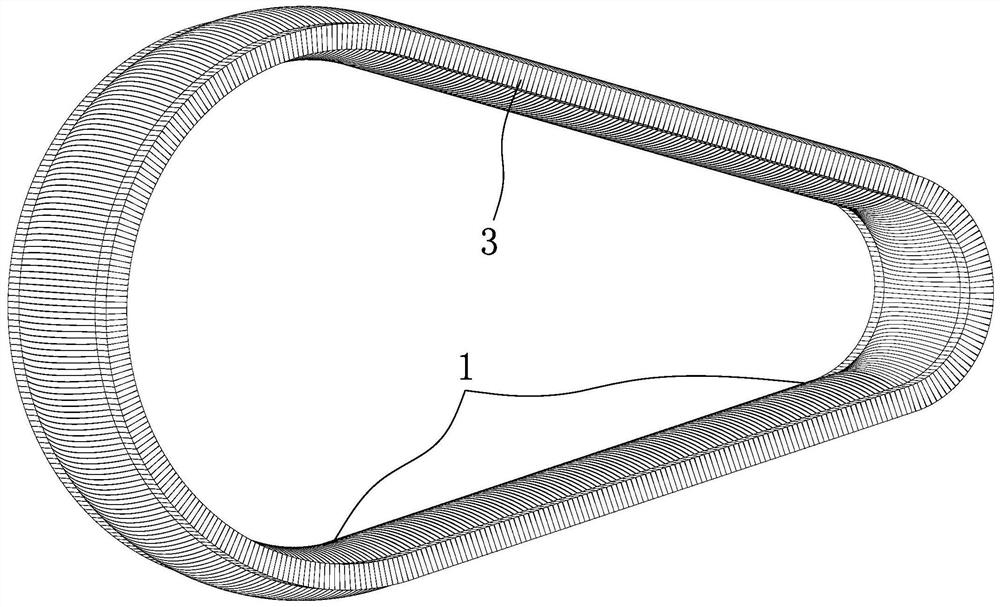
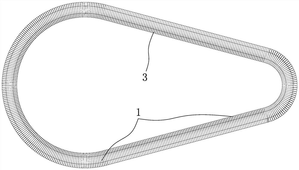
[0027] like Figure 1-12 and Figure 15 , 16 As shown, a movable-plate continuously variable transmission belt (1) includes: an annular carrier (2) and a transverse member (3) installed on the annular carrier (2), characterized in that: the transverse member ( 3) Continuously arranged and installed on the annular carrier (2), and can move laterally left and right on the axis of the annular carrier (2), so that the two sides of the drive belt can form tooth shapes of any shape and size , set transmission teeth on the surface of the transmission wheel, so as to realize gear meshing stepless transmission.

[0028] like Figure 4 , 7 , 10, and 12, the movable-plate continuously variable transmission belt (1) has at least one group of annular bearing bodies (2), and the transverse member (3) is provided with as many ring-shaped bearing bodies as the number of an...


PUM


Abstract

A continuously variable transmission driving belt with sliding vanes comprises annular bearing bodies and transverse parts installed on the annular bearing bodies and is characterized in that the transverse parts are continuously arranged and mounted on the annular bearing bodies and can move transversely leftwards and rightwards on the axes of the annular bearing bodies so that tooth profiles with the arbitrary shapes and sizes can be formed on the surfaces of the two sides of the driving belt. The continuously variable transmission driving belt with the sliding vanes has the beneficial effects that tooth engagement and continuously variable driving can be achieved, and the defects that a common continuously variable transmission driving belt driven by frictional force is small in transmitted torque, low in bearing capacity, poor in overload resistant and impact resistant performance and large in sliding rate, the mechanical efficiency is low, the power loss is large, transmitted power is limited, and the application range is limited are overcome.

Description

[0001] Technical field [0002] The invention relates to a power transmission belt, in particular to a power transmission belt suitable for a continuously variable transmission. Background technique [0003] At present, the transmission belt or chain of continuously variable transmission mostly adopts friction transmission, because of its small transmission torque, low load-carrying capacity, poor anti-overload and anti-impact performance, large slip rate, and low mechanical efficiency; some also have pulsating output and discontinuous power flow. Phenomenon; transmission of power needs to increase the pressure on the transmission belt to increase the friction, thus causing a large power loss, and causing the load of each bearing to increase, and the bearing is easy to be damaged; the effective contact surface for power transmission is small, Theoretically, it is line contact or point contact, and the local stress is large, which may easily cause scratches or glue on the worki...

Claims


Application Information

Patent Timeline
Patent Type & Authority Patents(China)
IPC IPC(8): F16G1/28F16G1/26
CPCF16G1/26F16G1/28
Inventor 不公告发明人
Owner 陈学琴
Why Eureka
Try Eureka