
Position fault diagnosis method for switch handle

A switch handle, fault diagnosis technology, applied in the direction of components with teeth, transmission control, belt/chain/gear, etc., can solve problems such as abnormal shift control

Inactive Publication Date: 2018-03-20
UNITED AUTOMOTIVE ELECTRONICS SYST
View PDF4 Cites 1 Cited by
  • Summary
  • Abstract
  • Description
  • Claims
  • Application Information

AI Technical Summary

Problems solved by technology

[0005] The purpose of the present invention is to provide a position fault diagnosis method of the switch handle to solve the problem that when the handle position sensor fails in the prior art, the automatic transmission control unit will perform abnormal shift control according to the wrong switch handle position signal The problem

Method used


Image

  • Position fault diagnosis method for switch handle
  • Position fault diagnosis method for switch handle

Examples


Embodiment Construction

[0020] The position fault diagnosis method of the switch handle proposed by the present invention will be further described in detail below in conjunction with the drawings and specific embodiments. Advantages and features of the present invention will be apparent from the following description and claims. It should be noted that all the drawings are in a very simplified form and use imprecise scales, and are only used to facilitate and clearly assist the purpose of illustrating the embodiments of the present invention.

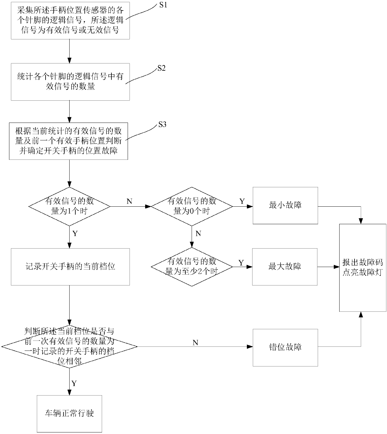
[0021] Please refer to figure 1 , which is a flow chart of the position fault diagnosis method of the switch handle of the present invention, as figure 1 As shown, the position fault diagnosis method of the switch handle, the switch handle has a handle position sensor, and the position fault diagnosis method of the switch handle specifically includes the following steps:

[0022] First, execute step S1 to collect the logic signal of each pin of the handle p...


PUM


Abstract

The invention provides a position fault diagnosis method for a switch handle. The position fault diagnosis method for the switch handle comprises the steps that logical signals of each pin of a handleposition sensor are gathered, and the logical signals are valid signals or invalid signals; the number of valid signals in the logical signals of each pin is counted; and the position fault of the switch handle is judged and confirmed according to the number of valid signals being currently counted and a previous valid handle position. By means of the position fault diagnosis method for the switch handle, the position fault of the switch handle can be accurately, quickly, reasonably and effectively diagnosed out, and then the accuracy of gear-shifting control of a control unit of an automaticgearbox is improved.

Description

technical field [0001] The invention relates to the technical field of automatic transmissions for automobiles, in particular to a method for diagnosing a position fault of a switch handle. Background technique [0002] Automatic transmission control unit (Transmission Control Unit, TCU) In order to follow the world's automobile technology and develop China's automobile industry, during the "Ninth Five-Year Plan" period, automobile electronic control technology was listed as a scientific and technological research project. Vehicle automatic transmission is an important part of automobile electronic control technology. The use of computer and power electronic drive technology to realize the automatic transmission of vehicles can eliminate the differences in the driver's shifting technology, reduce the labor intensity of the driver, improve driving safety, and improve the power and economy of the vehicle. The main functions of TCU include: 1) target gear (speed ratio) decisio...

Claims


Application Information

Patent Timeline
IPC IPC(8): F16H61/12F16H59/10
CPCF16H61/12F16H59/105F16H2061/1208
Inventor 王冰雪王振锁杨庆李淑英张宽宽邹绵意历宝录王宇明张庆洪王治松
Owner UNITED AUTOMOTIVE ELECTRONICS SYST
Features
  • Generate Ideas
  • Intellectual Property
  • Life Sciences
  • Materials
  • Tech Scout
  • Unparalleled Data Quality
  • Higher Quality Content
  • 60% Fewer Hallucinations
Learn More