Optical fiber distributing disc body, office direction optical routing device and office direction optical routing connection method
An optical fiber connection and optical fiber connector technology, applied in the field of communication, can solve problems such as poor flexibility of office-direction optical routing connection, and achieve the effect of reducing maintenance difficulty and cost
- Summary
- Abstract
- Description
- Claims
- Application Information
AI Technical Summary
Problems solved by technology
Method used
Image


Examples
Embodiment 1
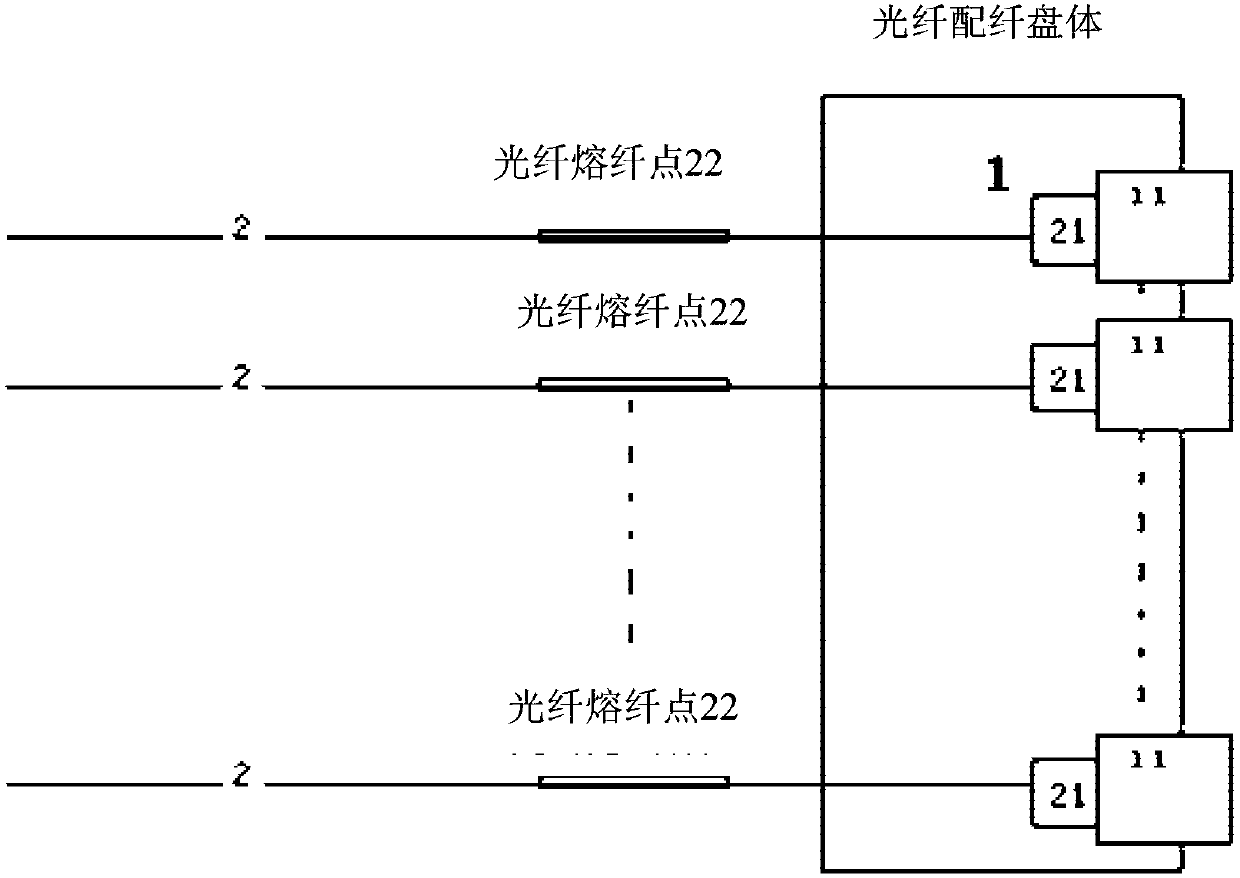
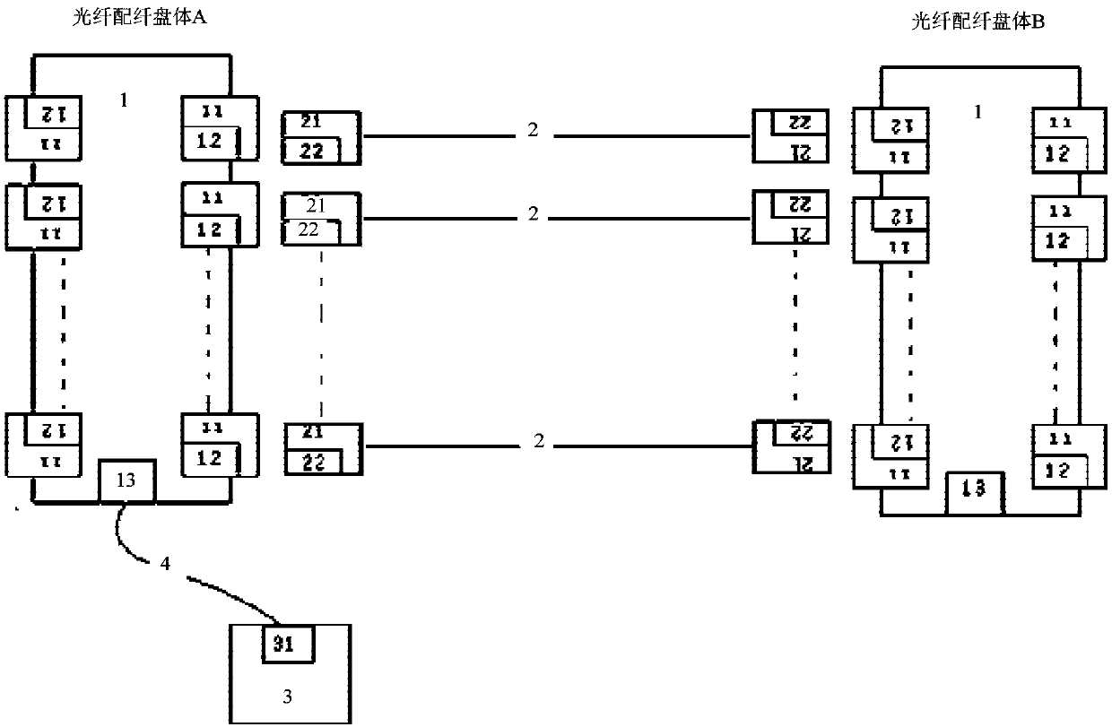
[0031] According to an embodiment of the present invention, an optical fiber distribution tray body is provided, and a plurality of optical fiber adapters are arranged on both sides of the optical fiber distribution tray body. The fiber optic adapters on both sides can be arranged side by side in one-to-one parallel arrangement, or any kind of arrangement, as long as one optical fiber is connected to the fiber distribution tray, there is a corresponding transmission outlet on the other side of the tray. In a specific device, it may include multiple optical fiber distribution trays, and the two ends of an optical fiber are respectively connected to different optical fiber distribution trays. In this way, both ends of the optical fiber are flexibly connected, which solves the problem of The problem of poor connection flexibility of the office-to-optical routing in the related art reduces the difficulty of maintenance or replacement.
[0032] image 3 It is a schematic connectio...
Embodiment 2
[0039] According to another embodiment of the present invention, there is also provided a local optical routing device, which is characterized in that it includes an optical fiber, and the optical fiber distribution tray described in Embodiment 1, wherein the optical fiber distribution tray Both sides are connected to the optical fiber through an optical fiber adapter.
[0040] Optionally, the optical fiber connectors at both ends of the optical fiber are provided with electronic labels, wherein the electronic label at one end of the optical fiber stores equipment information that needs to be connected to the optical fiber connector at the end, wherein, according to the device information to connect the fiber optic connector to the corresponding fiber optic adapter.
[0041] Optionally, the device information stored in the electronic tag includes one of the following:
[0042] Equipment serial number; equipment rack number; equipment frame number; equipment disk body number; ...
Embodiment 3
[0052] Figure 5 It is a local optical routing connection method according to an embodiment of the present invention, such as Figure 5 As shown, the steps are as follows:
[0053] S501, connect the optical fiber adapter on one side of the optical fiber distribution tray to the optical fiber connector of the first optical fiber, and connect the electronic label adapter on the same side of the optical fiber adapter to the electronic label of the first optical fiber;
[0054] S502. Connect the optical fiber adapter on the other side of the optical fiber distribution tray to the optical fiber connector of the second optical fiber, and connect the electronic label adapter on the same side of the optical fiber adapter to the electronic label of the second optical fiber.
[0055] Optionally, an external device is connected to the optical fiber distribution tray, wherein the external device is used to store the corresponding relationship between the optical fiber adapters and the op...
PUM
 Abstract
Description
Claims
Application Information
 - R&D
- Intellectual Property
- Life Sciences
- Materials
- Tech Scout
- Unparalleled Data Quality
- Higher Quality Content
- 60% Fewer Hallucinations
Browse by: Latest US Patents, China's latest patents, Technical Efficacy Thesaurus, Application Domain, Technology Topic, Popular Technical Reports.
© 2025 PatSnap. All rights reserved.Legal|Privacy policy|Modern Slavery Act Transparency Statement|Sitemap|About US| Contact US: help@patsnap.com