Stable holder based on MEMS gyroscope combination and control method

A control method and gyroscope technology, applied in the field of gimbal, can solve the problems of large temperature drift, low precision and high noise

Pending Publication Date: 2018-03-20
成都鼎信精控科技有限公司
View PDF7 Cites 17 Cited by
  • Summary
  • Abstract
  • Description
  • Claims
  • Application Information

AI Technical Summary

Problems solved by technology

Compared with inertial sensors of other principles, the advantages of MEMS inertial sensors are small size, low power consumption, and low cost. The disadvantages are low precisio

Method used


Image

  • Stable holder based on MEMS gyroscope combination and control method
  • Stable holder based on MEMS gyroscope combination and control method
  • Stable holder based on MEMS gyroscope combination and control method

Examples


Embodiment approach 1

[0076] A kind of stable cloud platform based on MEMS gyroscope combination, comprise cloud platform main body and be located at the gyroscope sensor on the cloud platform, described gyroscope sensor comprises:

[0077] Class A MEMS gyro sensor for angular velocity control;

[0078] Class B gyro sensor for attitude resolution and angle control.

[0079] In this embodiment, the sensor unit is composed of at least two types of MEMS gyroscope sensors, and each type of sensor includes at least three-axis angular velocity data. Class A MEMS gyroscope sensors have higher bandwidth and lower noise, and class B The gyroscope sensor has low temperature drift, the data of the class A MEMS gyroscope sensor is used for angular velocity control, the class B gyroscope sensor is used for attitude calculation and angle control, and the angular velocity data of the class A MEMS gyroscope sensor is used as control feedback The direct input of the gyroscope uses the angular velocity data of the ...

Embodiment approach 2

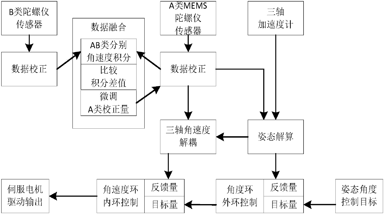
[0081] Such as figure 1 Shown, the control method based on the stable pan-tilt of MEMS gyroscope combination as claimed in claim 1, comprises the steps:

[0082] a. Calibrate the output data of the Class A MEMS gyro sensor and the Class B gyro sensor on the gimbal;

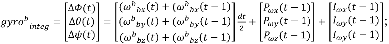
[0083] b. Perform data fusion on the output data of the calibrated Class A MEMS gyroscope sensor and the Class B gyroscope sensor;

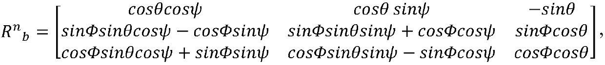
[0084] c. Perform attitude calculation on the three-axis acceleration data to obtain the current three-axis attitude angle data;

[0085] d. Execute the feedback algorithm of the outer loop control of the angle loop to obtain the output quantity, wherein the feedback quantity is the three-axis attitude angle data, and the target quantity is the attitude angle control target data;

[0086] e. Decoupling the three-axis attitude angle data and the output data of the corrected Class A MEMS gyroscope sensor to obtain the output value;

[0087] f. Execute the inner loop control feedback...

Embodiment approach 3

[0128] On the basis of embodiment 2, said step a also includes the following steps:

[0129]According to the pre-stored zero point offset data under different temperature conditions, the offset under the current temperature condition is fitted, and the angular velocity output data of the A-type MEMS gyro sensor and the B-type gyro sensor are calculated according to the offset Correction.


PUM


Abstract

The invention discloses a stable holder based on an MEMS gyroscope combination. The stable holder is composed of a class-A MEMS gyroscope sensor and a class-B gyroscope sensor. The class-A MEMS gyroscope sensor has high bandwidth and low noise. The class-B gyroscope sensor has low temperature drift and random drift. Multiple gyroscope sensors of different types are used to construct a combined sensor unit, and the advantages of different types of sensors are exerted through a reasonable control architecture and process. Therefore, the inertial measurement feedback and stability control performances are significantly improved, and the problem that the performance requirements are usually not satisfied in high-performance inertial attitude measurement and attitude stabilization is solved. The invention further discloses a control method of the stable holder based on an MEMS gyroscope combination.

Description

technical field [0001] The invention relates to the field of cloud platform technology, in particular to a stable platform based on a combination of MEMS gyroscopes and a control method thereof. Background technique [0002] With the development of micromechanical sensor (MEMS) technology, the performance of micromechanical inertial sensors has been continuously improved, and the application fields have been continuously expanded, especially in inertial attitude measurement, UAV flight control and gyro-stabilized gimbal. Compared with inertial sensors of other principles, the advantages of MEMS inertial sensors are small size, low power consumption, and low cost. The disadvantages are low precision, large temperature drift, and high noise. For high-performance inertial attitude measurement and attitude stabilization applications, often Unable to meet performance requirements. Contents of the invention [0003] In order to solve the problems existing in the prior art, the ...

Claims


Application Information

Patent Timeline
IPC IPC(8): G05D3/12G01C21/18
CPCG01C21/18G05D3/12
Inventor 焦志涛
Owner 成都鼎信精控科技有限公司
Why Eureka
Try Eureka