
A mobile communication terminal and its main board

A technology for mobile communication terminals and motherboards, applied in telephone communication, antenna grounding devices, telephone structures, etc., can solve problems such as increasing the difficulty of antenna unit tuning, affecting the grounding performance of antenna units, reducing the radiation efficiency of antenna units, etc., to reduce loss , Improve the grounding performance and reduce the difficulty of tuning

Active Publication Date: 2020-06-05
JRD COMM (SHENZHEN) LTD
View PDF5 Cites 0 Cited by
  • Summary
  • Abstract
  • Description
  • Claims
  • Application Information

AI Technical Summary

Problems solved by technology

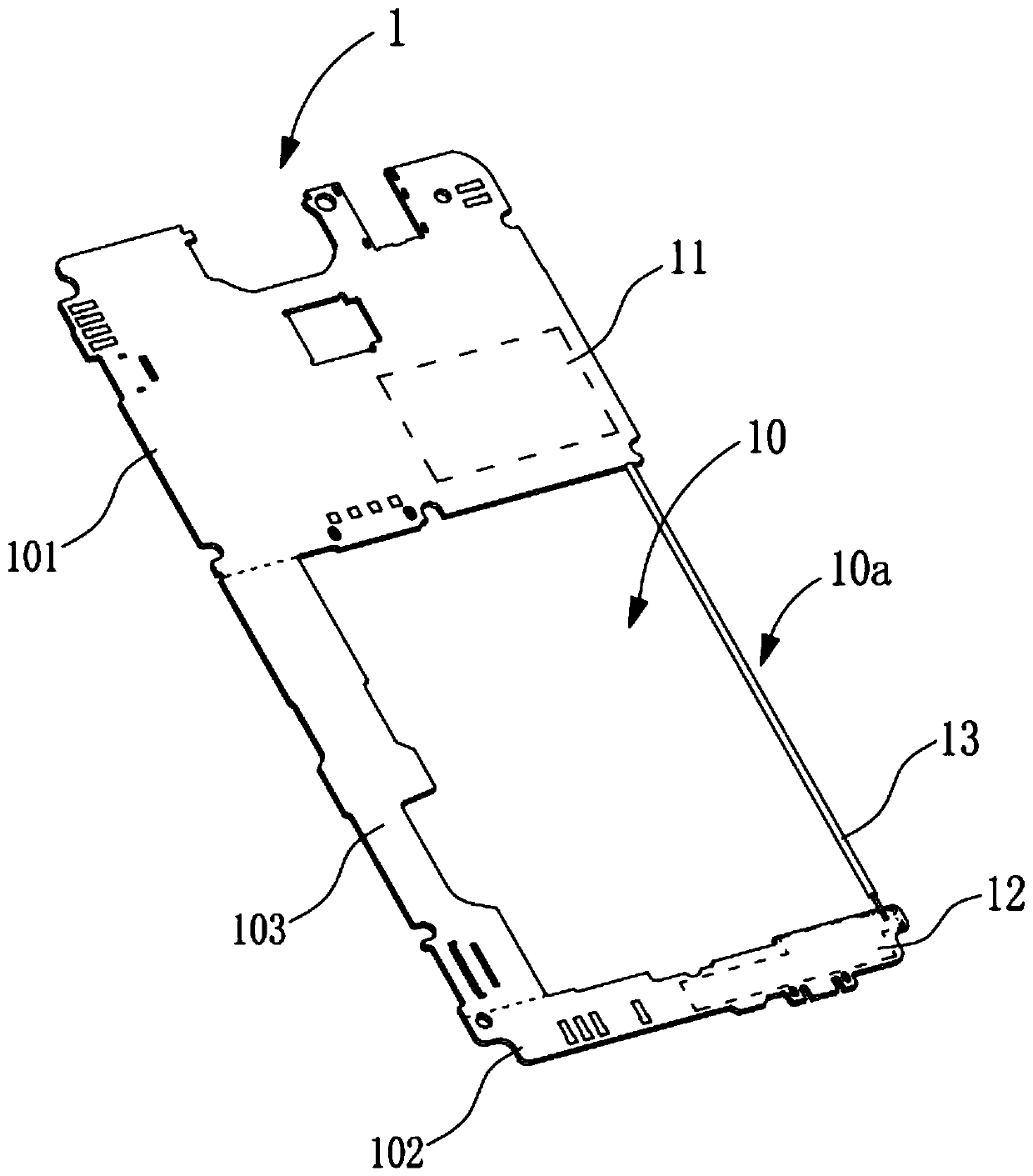
The above-mentioned structural setting makes it necessary for the negative charge at the ground end of the antenna unit to flow back from the second area to the ground of the radio frequency module located in the first area through the third area during the working process of the mobile communication terminal. At the end, the path of the current loop is relatively long, which affects the grounding performance of the antenna unit, thereby reducing the radiation efficiency of the antenna unit and increasing the tuning difficulty of the antenna unit

Method used


Image

  • A mobile communication terminal and its main board
  • A mobile communication terminal and its main board
  • A mobile communication terminal and its main board

Examples


Embodiment 1

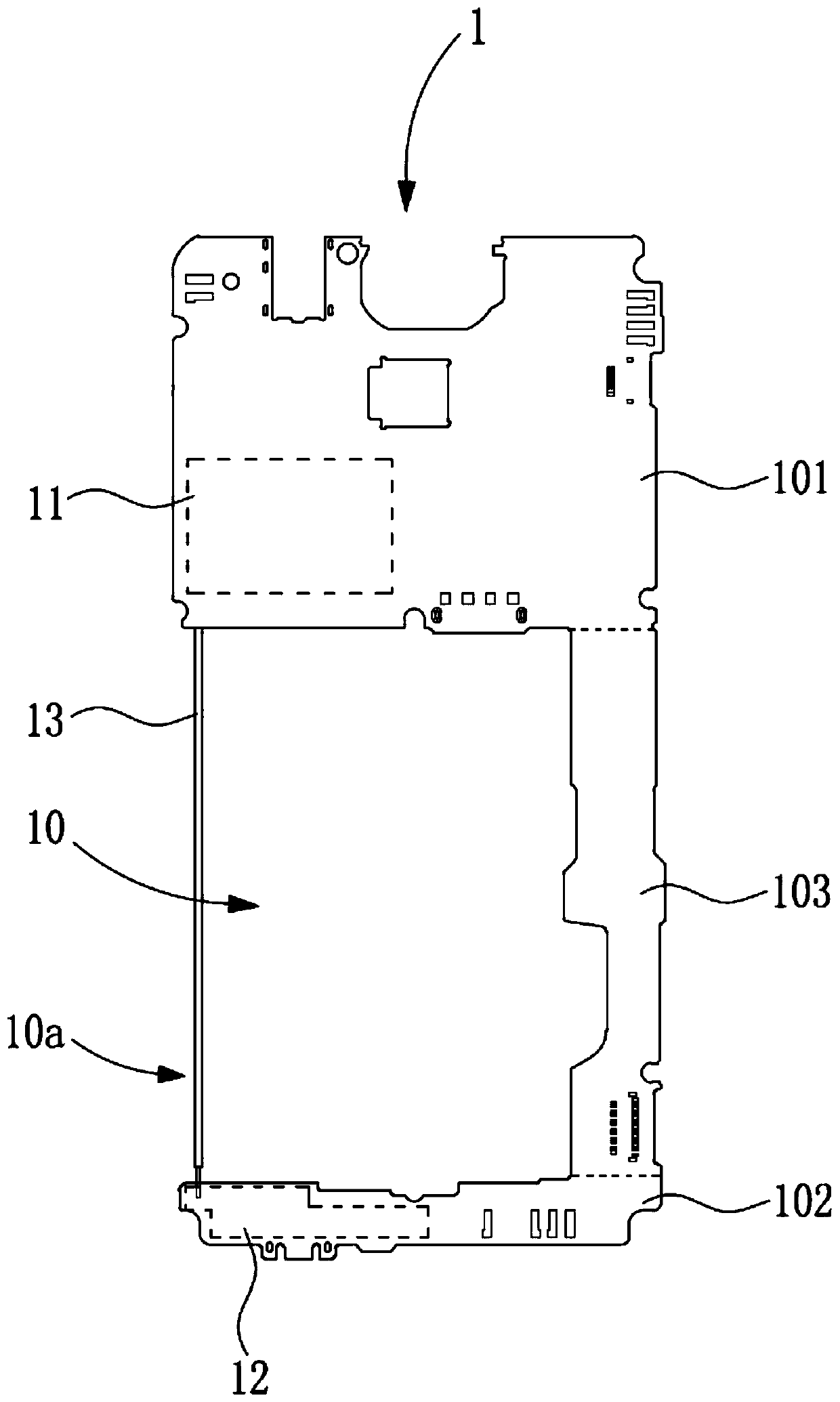
[0028] Such as figure 1 and figure 2 As shown, in this embodiment, the signal connector 13 is an iron wire. Under the premise of ensuring that the strength of the signal connector 13 is not easy to break, and that the negative charge at the antenna unit 12 can maintain a sufficient return velocity on the signal connector 13, the iron should be as far as possible. The guide wire is designed to be thinner, specifically, the diameter of the iron guide wire is not greater than 0.5mm.

[0029] Further, the iron wire is arranged on the edge of the opening side 10 a opposite to the third area 103 on the escape notch 10 . In order to ensure the radiation performance of the antenna unit 12, generally when designing a mobile communication terminal, the antenna unit 12 should be set as close as possible to the side of the mobile communication terminal, therefore, the iron wire is close to the antenna unit 12, in order to shorten the negative charge return path as much as possible, th...

Embodiment 2

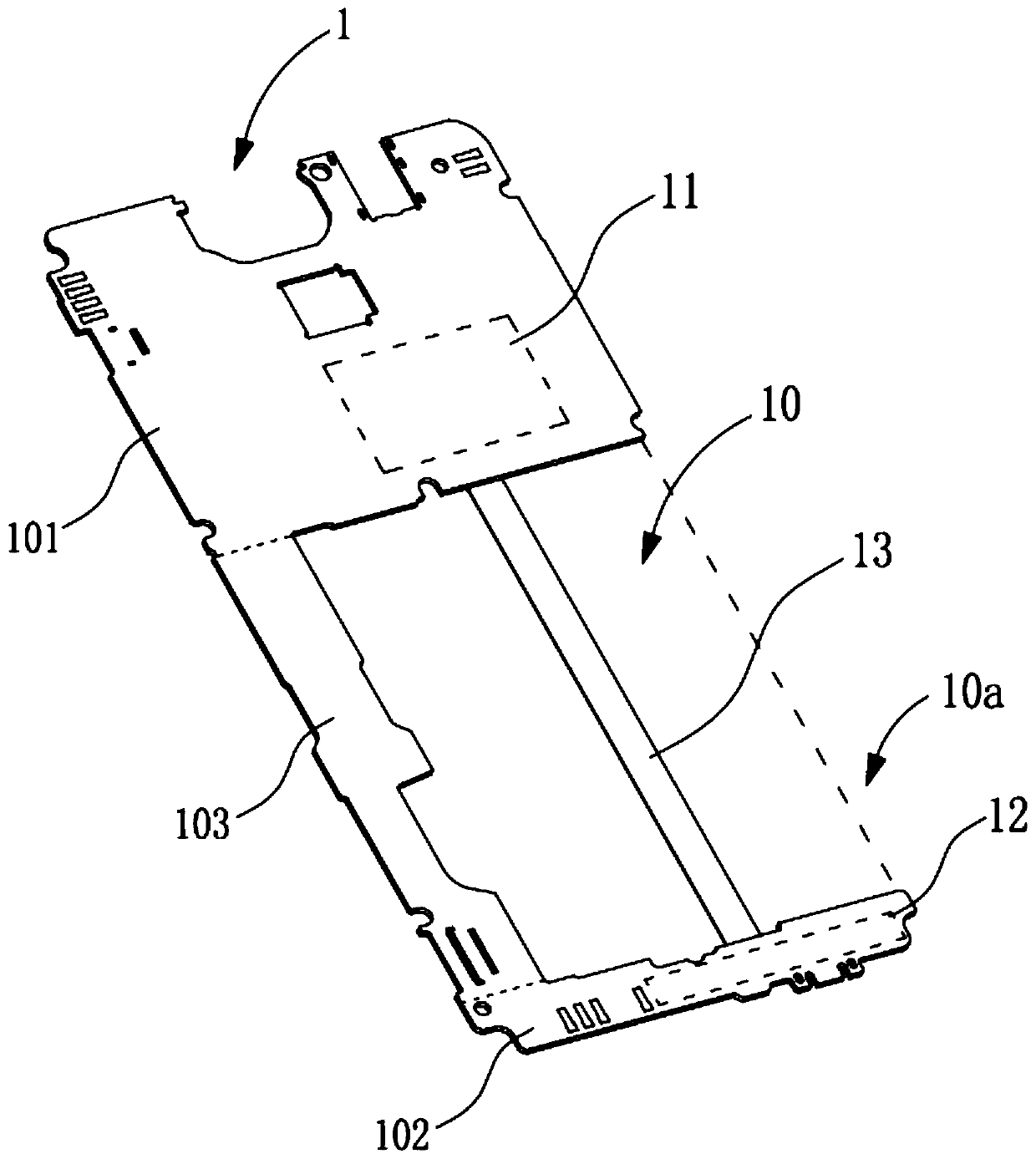
[0031] Such as image 3 and Figure 4 As shown, in this embodiment, the signal connector 13 is copper foil. At room temperature of 20°C, the resistivity of copper is 1.75×10 -8 Ω·m, while the resistivity of iron is 9.78×10 -8 Ω·m, therefore, the conductivity of copper is better than that of iron, and the signal connector 13 is made of copper material, which can further increase the speed at which the negative charge at the antenna unit 12 returns to the radio frequency module 11 , and the price of copper is lower than that of iron, which is conducive to cost reduction.

[0032] Similarly, in order to save the available space and cost inside the mobile communication terminal, the copper foil should be designed to be thinner as much as possible, but if the copper foil is too thin, it is easy to break, so the copper foil The cross-section needs to be kept within a certain length. Specifically, the length of the cross section of the copper foil is 3mm˜5mm.

[0033] In this e...


PUM


Abstract

The invention discloses a mobile communication terminal and a mainboard thereof. A signal connection piece is arranged on a PCB and stretches over an avoidance gap of the PCB, is connected with a first region and a second region at two sides of the avoidance gap respectively, and is communicated with a radio frequency module in the first region and an antenna unit in the second region; and the negative charge of a grounding end of the antenna unit can flow back to the ground end of the radio frequency module by a shortest path through the signal connection piece, so that the grounding performance of the antenna unit is improved, loss is lowered, the radiation efficiency of the antenna unit is improved, and the antenna unit is easier to tune.

Description

technical field [0001] The invention relates to the technical field of mobile communication terminals, in particular to a mobile communication terminal and a main board thereof. Background technique [0002] In existing mobile communication terminals, the main board often adopts the following structural configuration, the main board includes a PCB board, the PCB board is provided with an avoidance gap for assembling the battery, and the PCB board includes a first area, a second area and a third area, so The first area is provided with a radio frequency module, the second area is provided with an antenna unit, the first area and the second area are located on opposite sides of the avoidance gap, and the third area is located at the side of the avoidance gap The other side connects the first area and the second area to each other. The above-mentioned structural setting makes it necessary for the negative charge at the ground end of the antenna unit to flow back from the secon...

Claims


Application Information

Patent Timeline
Patent Type & Authority Patents(China)
IPC IPC(8): H04M1/02H01Q1/48
CPCH01Q1/48H04M1/026H04M1/0277
Inventor 陈卫
Owner JRD COMM (SHENZHEN) LTD
Learn More