Machine head cutter swing arm and connection rod device

A technology of connecting rod device and cutter, applied in shearing device, shearing machine equipment, metal processing equipment and other directions, can solve the problems of high energy consumption, low control precision, high noise, etc., and achieve the effect of strong rigidity

Pending Publication Date: 2018-03-23
东莞市超音速智能切割科技有限公司
View PDF0 Cites 0 Cited by
  • Summary
  • Abstract
  • Description
  • Claims
  • Application Information

AI Technical Summary

Problems solved by technology

Material cutting devices are used in many fields. Traditional cutting devices mostly use cylinders as power mechanisms, which mainly have the disadvantages of high noise, low control precision, and high energy consumption.

Method used


Image

  • Machine head cutter swing arm and connection rod device
  • Machine head cutter swing arm and connection rod device

Examples


Embodiment Construction

[0016] The present invention will be further described below according to the accompanying drawings and specific embodiments, but the embodiments of the present invention are not limited thereto.

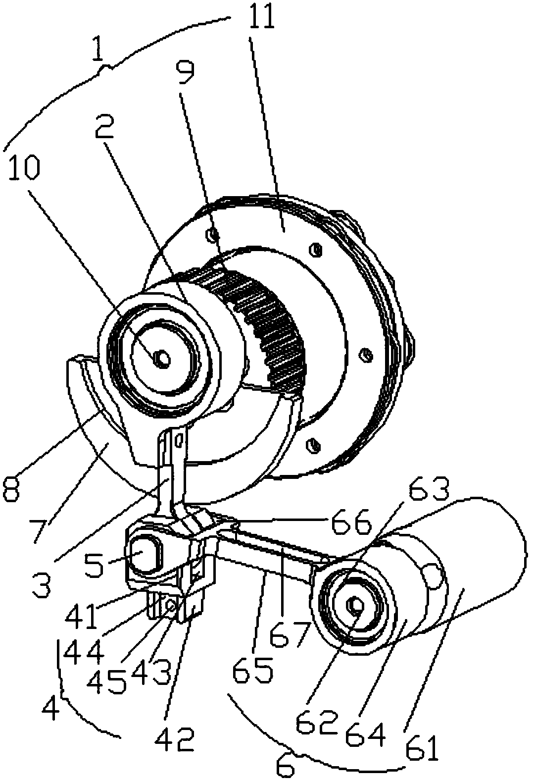
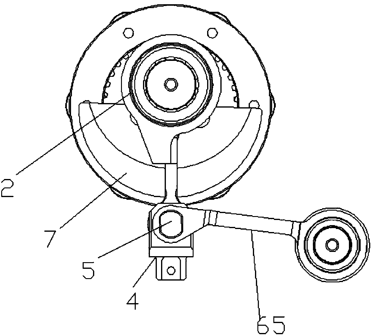
[0017] Such as figure 1 and figure 2 As shown, a head cutter swing arm linkage device includes a cam transmission mechanism 1, and a cam 2 of the cam transmission mechanism 1 is connected with a connecting rod 3 that is controlled by the cam transmission mechanism 1 to continuously move vertically up and down. The lower end of 3 is movably connected on a card arm 4, and card arm 4 is articulated by pin 5 and is used for controlling the vertical movement distance of connecting rod 3 and the swing arm mechanism 6 for offsetting connecting rod 3 swing force.

[0018] Preferably, the swing arm mechanism 6 includes a swing arm support 61, the end of the swing arm support 61 is provided with a tip 62 with a diameter smaller than the swing arm support 61 diameter, the tip 62 is sleeved w...


PUM


Abstract

The invention discloses a connecting rod device for swing arm of machine head cutter, which comprises a cam transmission mechanism. The cam of the cam transmission mechanism is connected with a connecting rod which is controlled by the cam transmission mechanism to continuously move vertically up and down. The lower end of the connecting rod is movably connected to On one card arm, the card arm is flexibly hinged by pins to a swing arm mechanism for controlling the vertical up and down movement distance of the connecting rod and for counteracting the swinging force of the connecting rod. The present invention adopts a swing arm mechanism, which is used to control the vertical vertical movement distance of the connecting rod, and to offset the swing force of the connecting rod, so that the connecting rod drives the cutter to always move vertically up and down, and the material used in the swing arm mechanism is titanium alloy material , stronger steel. When the cam rotates, it drives the connecting rod to move back and forth, and the cam slides along the semicircular groove to further stabilize the movement track of the connecting rod.

Description

technical field [0001] The invention relates to a cutting device, in particular to a connecting rod device for swinging arms of a head cutter. Background technique [0002] Currently. Material cutting devices are used in many fields. Traditional cutting devices mostly use cylinders as power mechanisms, which mainly have the disadvantages of high noise, low control precision, and high energy consumption. Contents of the invention [0003] The object of the present invention is to provide a head cutter swing arm linkage device for the above-mentioned defects of the prior art. [0004] In order to solve the above-mentioned defects of the prior art, the technical solution provided by the present invention is: a head cutter swing arm linkage device, including a cam transmission mechanism, the cam of the cam transmission mechanism is connected with a cam that is controlled by the cam transmission mechanism. A connecting rod that continuously moves vertically up and down, the l...

Claims


Application Information

Patent Timeline
Patent Type & Authority Applications(China)
IPC IPC(8): B23D15/12
CPCB23D15/12
Inventor 邹今令
Owner 东莞市超音速智能切割科技有限公司
Why Eureka
Try Eureka