Installing structure of circuit board in refrigerating compressor

A technology for refrigeration compressors and installation structures, applied to compressors, refrigerators, refrigeration components, etc., can solve the problems of poor cooling effect, high temperature of circuit board boxes, and far wiring, etc., to achieve lower temperature and better heat absorption Effect

Pending Publication Date: 2018-03-23
NANJING CIGU TECH CORP LTD
View PDF7 Cites 1 Cited by
  • Summary
  • Abstract
  • Description
  • Claims
  • Application Information

AI Technical Summary

Problems solved by technology

The circuit board box of the existing refrigeration compressor is not installed on the main unit of the refrigeration compressor, but placed separately, the electrical components emit heat, and the internal temperature of the circuit board box is relatively high, which needs to be cooled and dissipated, and the emitted heat is discharged into the room, causing the room temperature to rise high
In addition, heat dissipation fins need to be processed on the existing circuit board box, and the cooling effect of the fan is not good, and the wiring between the two electrical connectors on the refrigeration compressor casing and the circuit board box is also relatively far away.

Method used


Image

  • Installing structure of circuit board in refrigerating compressor
  • Installing structure of circuit board in refrigerating compressor
  • Installing structure of circuit board in refrigerating compressor

Examples


Embodiment Construction

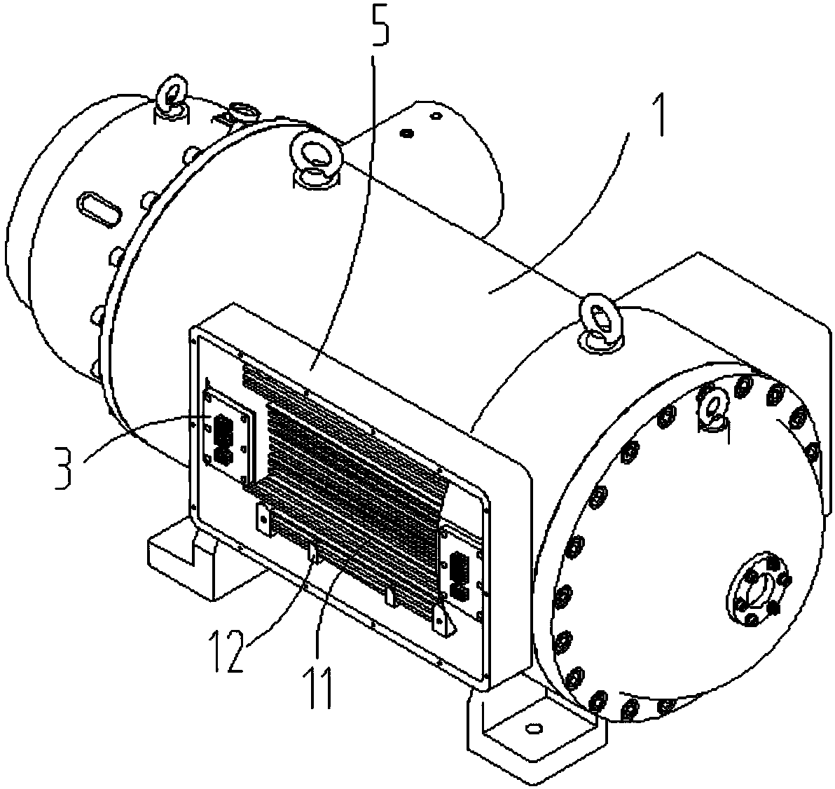
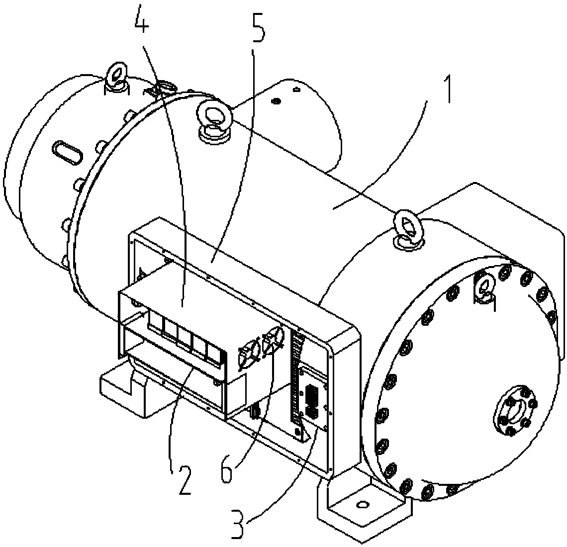
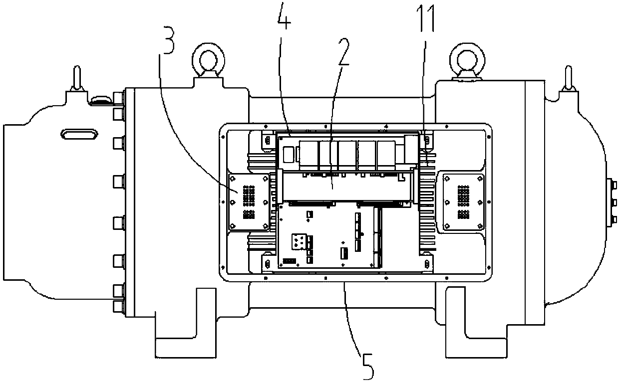
[0012] The present invention will be further described below in conjunction with the accompanying drawings.

[0013] Such as Figure 1 to Figure 4 , the invention discloses a circuit board installation structure in a refrigeration compressor, including a refrigeration compressor casing 1, a circuit board 2, an electrical connector 3, a circuit board support 4, a frame body 5 and a cooling fan 6, two electrical connectors 3 is fixedly connected to the outer wall of the refrigeration compressor housing 1, and the two electrical connectors 3 are connected to the circuit board 2. The frame body 5 is fixedly connected to the outer wall of the refrigeration compressor casing 1, and the cooling fins 11 are arranged on the outer wall of the refrigeration compressor casing 1. The heat dissipation fins 11 are placed in the frame body 5, and the two electrical connectors 3 are symmetrical. Located on both sides of the cooling fins 11 , the circuit board support 4 is fixed on the cooling...


PUM


Abstract

The invention discloses an installing structure of a circuit board in a refrigerating compressor. The installing structure comprises a refrigerating compressor shell, the circuit board and electric connecting devices. The two electric connecting devices are fixedly connected to the outer wall of the refrigerating compressor. The two electric connecting devices are connected with the circuit board.The installing structure further comprises a circuit board support, a frame body and a heat dissipating fan. The frame body is fixedly connected to the outer wall of the refrigerating compressor shell. Heat dissipating fins are arranged on the outer wall of the refrigerating compressor shell and arranged in the frame body. The two electric connecting devices are symmetrically located on the two sides of the heat dissipating fins. The circuit board support is fixed to the heat dissipating fins through screws. The circuit board is fixed into the circuit board support. The heat dissipating fan is fixed to the side wall of the circuit board support. The installing structure is beneficial for lowering the temperature of electric devices on the circuit board, the electric connecting devices onthe refrigerating compressor shell and the circuit board are connected more closely, and the use effect is good.

Description

Technical field: [0001] The invention relates to an installation structure of a circuit board in a refrigeration compressor. Background technique: [0002] Several circuit boards are arranged in the circuit board box of the refrigeration compressor, and electrical components are arranged on the circuit boards. The circuit board box of the existing refrigeration compressor is not installed on the main unit of the refrigeration compressor, but placed separately, the electrical components emit heat, and the internal temperature of the circuit board box is relatively high, which needs to be cooled and dissipated, and the emitted heat is discharged into the room, causing the room temperature to rise high. In addition, heat dissipation fins need to be processed on the existing circuit board box, and the fan is cooled, so the cooling effect is not good, and the wiring between the two electrical connectors on the refrigeration compressor casing and the circuit board box is relative...

Claims


Application Information

Patent Timeline
IPC IPC(8): F25B31/00H05K7/20
CPCH05K7/20136H05K7/20409F25B31/006
Inventor 包金哲刘淑云吴立华董继勇
Owner NANJING CIGU TECH CORP LTD
Why Eureka
Try Eureka