
A mems gas differential pressure sensor

A differential pressure sensor and gas technology, applied in the field of sensors, can solve the problems of low sensitivity and achieve the effects of high sensitivity, small zero drift and high dynamic response speed

Active Publication Date: 2019-11-26
南京元感微电子有限公司
View PDF9 Cites 0 Cited by
  • Summary
  • Abstract
  • Description
  • Claims
  • Application Information

AI Technical Summary

Problems solved by technology

[0004] The present invention proposes a MEMS gas differential pressure sensor, and its purpose is to solve the problem of low sensitivity of existing differential pressure sensors

Method used


Image

  • A mems gas differential pressure sensor
  • A mems gas differential pressure sensor
  • A mems gas differential pressure sensor

Examples


Embodiment Construction

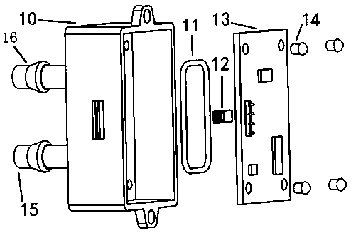
[0018] MEMS gas differential pressure sensor, its structure includes a housing 10, a sealing rubber ring 11, a chip 12, and a circuit board 13; wherein, there is a groove in the middle of the housing 10, the chip 12 is in the groove, and the circuit board 13 is covered above the groove , There is a sealing rubber ring 11 between the circuit board 13 and the housing 10 .

[0019] The circuit board 13 and the housing 10 are fixedly connected by fixing screws 14 , or the circuit board 13 and the housing 10 are directly bonded with a sealant.

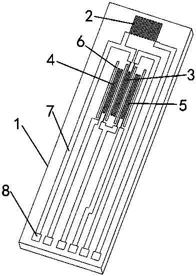
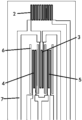
[0020] The chip 12 includes a substrate 1, an environmental resistance 2, a heating resistance 3, a first temperature detection resistance 4, a second temperature detection resistance 5, four heat insulation grooves 6, several wires 7, lead pads 8, and a back chamber 9 ; Wherein, the environment resistance 2, the heating resistance 3, the first temperature detection resistance 4, and the second temperature detection resistance 5 are on the ...


PUM


Abstract

The invention provides an MEMS gas differential pressure sensor of which the structure comprises a shell, a sealed rubber ring, a chip and a circuit board. The middle of the shell is provided with a groove. The chip is arranged in the groove. The circuit board covers the groove. The sealed rubber ring is arranged between the circuit board and the shell. The advantages of the MEMS gas differentialpressure sensor are that 1) the low differential pressure of 0.1Pa can be detected in comparison with the diaphragm differential pressure sensor, and the sensor also has the advantages of high sensitivity, low zero drift and high dynamic response speed; and 2) the sensor can be applied to the application field of medical equipment and heating and ventilating and air conditioning.

Description

technical field [0001] The invention relates to a MEMS (Micro-Electro-Mechanical System) gas differential pressure sensor, in particular to a gas differential pressure sensor based on the principle of heat conduction and implemented by MEMS technology, which belongs to the technical field of sensors. Background technique [0002] Differential pressure sensors can be applied to gas flow detection in pipelines. For example, adding an orifice structure to the pipeline will form a differential pressure upstream and downstream of the orifice when there is airflow passing through it. Venturi structures can also be used. When there is airflow flowing through, Differential pressure will also be formed at the thicker and thinner positions of the pipeline; the differential pressure sensor can be used to measure the differential pressure, and the flow rate of the gas in the pipeline can be inferred; the differential pressure sensor can also be used for air purifier filter blockage In t...

Claims


Application Information

Patent Timeline
Patent Type & Authority Patents(China)
IPC IPC(8): G01L13/00
CPCG01L13/00
Inventor 谷永先吴孔培黄从贵瞿惠琴
Owner 南京元感微电子有限公司
Learn More