
A fatigue testing machine suitable for equipment wire clips

A fatigue testing machine and equipment wire clip technology, applied in the field of fatigue testing machines, can solve problems such as the inability to guarantee the safety of use

Active Publication Date: 2019-10-29
ELECTRIC POWER SCI RES INST OF STATE GRID XINJIANG ELECTRIC POWER +1
View PDF4 Cites 0 Cited by
  • Summary
  • Abstract
  • Description
  • Claims
  • Application Information

AI Technical Summary

Problems solved by technology

It can be seen that the safety of use cannot be guaranteed under the condition of meeting the existing national standards

Method used


Image

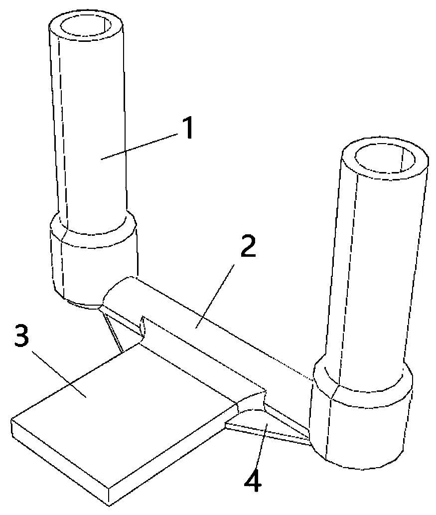
  • A fatigue testing machine suitable for equipment wire clips
  • A fatigue testing machine suitable for equipment wire clips
  • A fatigue testing machine suitable for equipment wire clips

Examples


Embodiment Construction

[0026] The following will clearly and completely describe the technical solutions in the embodiments of the present invention with reference to the accompanying drawings in the embodiments of the present invention. Obviously, the described embodiments are only some, not all, embodiments of the present invention. Based on the embodiments of the present invention, all other embodiments obtained by those of ordinary skill in the art without creative efforts shall fall within the protection scope of the present invention.

[0027] It should be noted that, in this document, relational terms such as first and second are used only to distinguish one entity or operation from another entity or operation, and do not necessarily require or imply any relationship between these entities or operations. any such actual relationship or sequence exists. Furthermore, the term "comprises", "comprises" or any other variation thereof is intended to cover a non-exclusive inclusion such that a proce...


PUM


Abstract

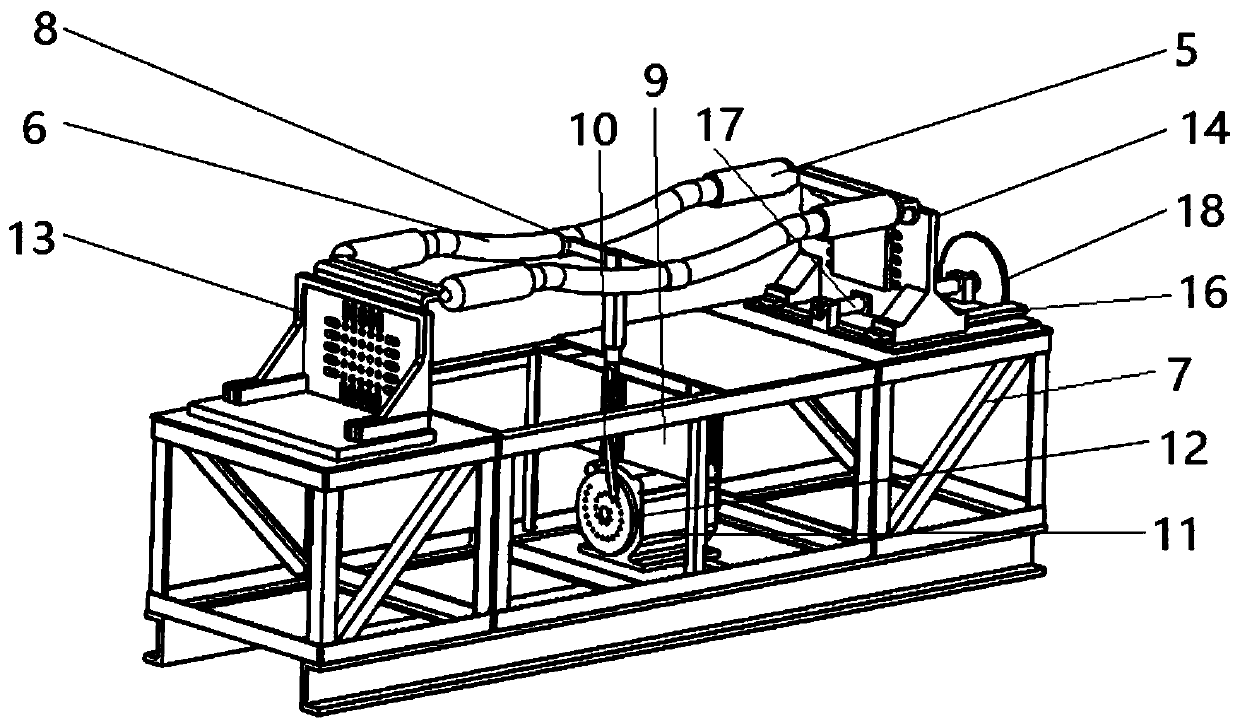
The invention provides a fatigue tester suitable for device wire clamps. Two to-be-tested device wire clamps are connected via a wire. The fatigue tester includes a box-shaped frame base, two clampingplates, a pull rod, a sliding base, a transmission rod and a rotating wheel driven by a motor. The two clamping plates correspond to the two to-be-tested device wire clamps one to one. Each clampingplate clamps the corresponding to-be-tested device wire clamp. The two clamping plates include a fixed clamp plate fixed to the top of the frame base and a movable clamping plate arranged on the top of the frame base slidably. The upper end of the pull rod is provided with a movable ring sleeve for allowing the wire to pass therethrough. The lower end of the pull rod is connected with the slidingbase. The sliding base is arranged on the frame base vertically movably. The rotating wheel is provided with an eccentric hole. One end of the transmission rod is connected with the sliding base, andthe other end of the transmission rod is connected with the eccentric hole. The fatigue tester is beneficial to the service performance evaluation, the life assessment, the material plan formulation of the device wire clamps, and has important significance for the reliable operation and accident prevention of a power grid line.

Description

technical field [0001] The invention belongs to the technical field of electric equipment manufacturing and processing, and in particular relates to a fatigue testing machine suitable for equipment wire clips. Background technique [0002] The equipment clamp is used to connect the down-lead of the busbar to the outlet terminals of electrical equipment (such as transformers, circuit breakers, transformers, isolating switches, wall bushings, etc.), and is widely used. Nowadays, the outlet terminals of commonly used electrical equipment are copper and aluminum, and the lead wires are mostly aluminum stranded wires or steel-cored aluminum stranded wires. Therefore, the equipment clamps are divided into two types: aluminum equipment clamps and copper-aluminum transition equipment clamps. series. Among them, the aluminum equipment clamps are divided into compression type and bolt type according to different installation methods and structural forms. Each type of clamp is divide...

Claims


Application Information

Patent Timeline
Patent Type & Authority Patents(China)
IPC IPC(8): G01M13/00
CPCG01M13/00
Inventor 刘阳李勇杰肖文凯何鹏王晗马鹏飞翟显马勤勇孙谊媊何成李伟郑义赵建平郜宁徐凯王欣欣游溢崔晓东陈东娃王宗江赵普志杨柱石廖杰
Owner ELECTRIC POWER SCI RES INST OF STATE GRID XINJIANG ELECTRIC POWER
Learn More