
Detection method and device of surface-mounted bonding pad

A detection method and pad technology, applied in special data processing applications, instruments, electrical digital data processing, etc., can solve problems such as missed detection and low efficiency, and achieve the effect of improving work efficiency, shortening modification time, and avoiding poor welding.

Inactive Publication Date: 2018-03-23
SUZHOU CENTEC COMM CO LTD
View PDF6 Cites 4 Cited by
  • Summary
  • Abstract
  • Description
  • Claims
  • Application Information

AI Technical Summary

Problems solved by technology

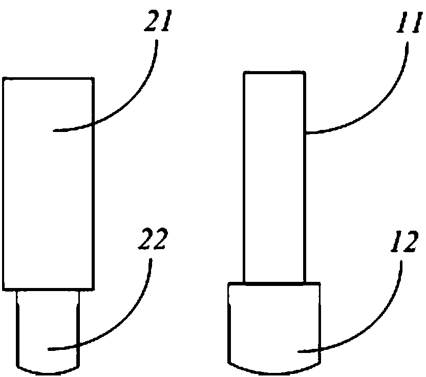
Therefore, in the design stage of the PCB board, it is necessary to ensure that the width of all surface mount pads is greater than the width of the connection line connected to it (for example, if figure 1 As shown, the width of the first connection line 11 is smaller than the width of the first surface mount pad 12, which meets the requirements; while the width of the second connection line 21 is greater than the width of the second surface mount pad 22, which does not meet the requirements), In the prior art, the designer usually conducts the detection manually. Since the number of surface mount pads is generally relatively large, it may cause missed detection and the efficiency is low.

Method used


Image

  • Detection method and device of surface-mounted bonding pad
  • Detection method and device of surface-mounted bonding pad
  • Detection method and device of surface-mounted bonding pad

Examples


Embodiment Construction

[0020] The present invention will be described in detail below in conjunction with various embodiments shown in the drawings. However, these embodiments do not limit the present invention, and any structural, method, or functional changes made by those skilled in the art according to these embodiments are included in the protection scope of the present invention.

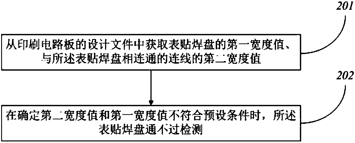
[0021] An embodiment of the present invention provides a detection method for surface mount pads, such as figure 2 shown, including the following steps:

[0022] Step 201: Obtain the first width value of the surface mount pad and the second width value of the connection line connected to the surface mount pad from the design file of the printed circuit board;

[0023] Here, the surface mount pads may be located on the top surface (ie, the TOP surface) or the bottom surface (ie, the Bottom surface). When the starting point or end point of the connection line is the same as the coordinates of the surface mount pad,...


PUM


Abstract

The invention provides a detection method of a surface-mounted bonding pad. The detection method comprises the following steps of obtaining a first width value of the surface-mounted bonding pad and asecond width value of a connection line communicated with the surface-mounted bonding pad from a design file of a printed circuit board; when it is determined that the second width value and the first width value do not conform to a preset condition, regarding that the surface-mounted bonding pad fails the detection. By means of the detection method of the surface-mounted bonding pad, all detection surface-mounted bonding pads can be automatically detected, thus the problems can be quickly located, the correction time is greatly shortened, the work efficiency is improved, the risk of poor welding is avoided, and the product yield rate is increased.

Description

technical field [0001] The invention relates to the technical field of printed circuit boards, in particular to a detection method and device for surface mount pads. Background technique [0002] Usually, a PCB (Printed Circuit Board, printed circuit board) is provided with pads and wiring for connecting multiple pads, wherein the pads may be surface mount pads. When soldering electronic components, in order to prevent the heat dissipation from being too fast and the temperature of the solder to cool down too fast, resulting in virtual soldering; at the same time, in order to prevent the solder mask from being insufficiently precise, causing the solder to flow, which may increase the risk of short circuit; surface mount pads are required The width of is greater than the width of the connecting line. Therefore, in the design stage of the PCB board, it is necessary to ensure that the width of all surface mount pads is greater than the width of the connection line connected to...

Claims


Application Information

Patent Timeline
Patent Type & Authority Applications(China)
IPC IPC(8): G06F17/50
CPCG06F30/398G06F2115/06
Inventor 朱光刘丹曾照武
Owner SUZHOU CENTEC COMM CO LTD
Learn More