Prediction method and system for drilling axial force of laminated structure

A technology of layered structure and prediction method, applied in the field of workpiece processing, can solve the problem of inability to handle prediction of cutting force of heterogeneous materials, inability to ensure the prediction accuracy of drilling axial force, and inability to solve the drilling force curve in the layered interface area, etc. question

Active Publication Date: 2018-03-23
NORTHWESTERN POLYTECHNICAL UNIV
View PDF5 Cites 8 Cited by
  • Summary
  • Abstract
  • Description
  • Claims
  • Application Information

AI Technical Summary

Problems solved by technology

When this method is used to predict the axial force of thin-walled composite-metal laminated structures, there are the following problems: 1) It is impossible to solve the drilling force curve of the laminate interface area, which is near the contact surface of the composite material and the metal In this area, the drilling edge simultaneously cuts composite materials and metal materials with changing proportions. The existing methods cannot deal with the cutting force prediction of heterogeneous materials; 2) The influence of structural deformation on the cutting process cannot be considered, and the thin-walled Deformation and springback occur under the action of the drilling axial force, which changes the relative speed between the workpiece and the tool, and makes the drilling force curve show a different shape, that is, the existing method does not include the workpiece stiffness as an influencing factor into the prediction in the model
[0003] To sum up, the existing methods for predicting the drilling axial force of the stacked structure cannot guarantee the prediction accuracy of the drilling axial force during the whole drilling process of the stacked structure.

Method used

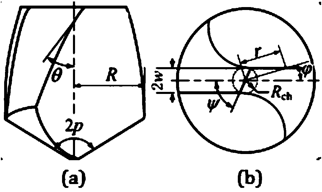

Image

  • Prediction method and system for drilling axial force of laminated structure
  • Prediction method and system for drilling axial force of laminated structure
  • Prediction method and system for drilling axial force of laminated structure

Examples


Embodiment Construction

[0077] The object of the present invention is to provide a method and system for predicting the drilling axial force of a stacked structure, so as to ensure the prediction accuracy of the drilling axial force during the whole drilling process of the stacked structure.

[0078] In order to make the above objects, features and advantages of the present invention more comprehensible, the invention will be further described in detail below in conjunction with the accompanying drawings and specific embodiments.

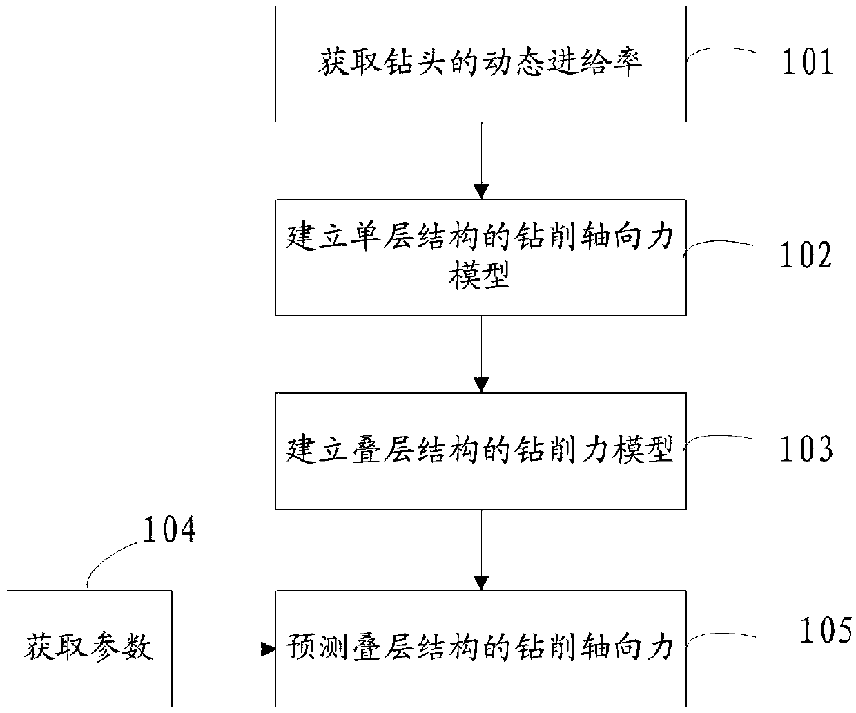
[0079] like figure 1 As shown, the present invention provides a method for predicting the drilling axial force of a laminated structure, and the method for obtaining the axial force of the laminated structure drilling includes the following steps:

[0080] Step 101, obtain the dynamic feed rate of the drill according to the additional feed rate caused by the deformation of the single-layer structure;

[0081] In step 102, according to the dynamic feed rate, a single-layer...


PUM


Abstract

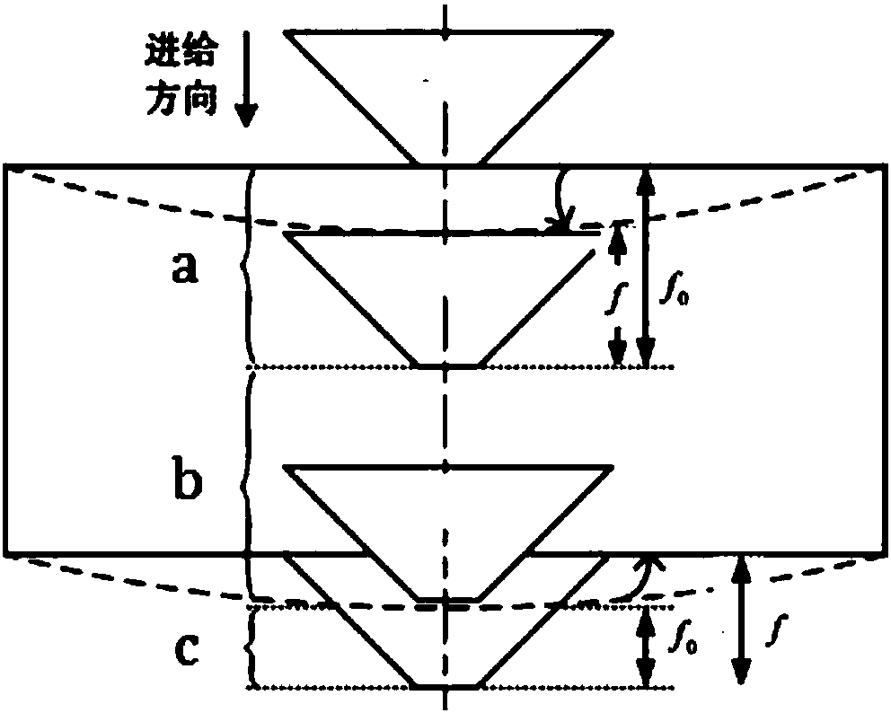
The invention discloses a prediction method and system for drilling axial force of a laminated structure. The method comprises the steps that according to an additional feeding rate caused by deformation of a single-layer structure, a dynamic feeding rate of a drill bit is obtained; according to the dynamic feeding rate, an infinitesimal drilling blade is adopted to establish a drilling axial force model of the single-layer structure; the drilling process of the laminated structure is divided into different stages, and a drilling force model of the laminated structure at each stage is established according to the drilling axial force model of the single-layer structure; physical parameters of the laminated structure, physical parameters of the drill bit and a given feeding rate of the drill bit are acquired; and according to the physical parameters of the laminated structure, the physical parameters of the drill bit and the given feeding rate of the drill bit, the drilling force modelof the laminated structure at each stage is utilized to predict the drilling axial force of the laminated structure at each stage. In this way, prediction of the drilling axial force of the laminatedstructure at all the stages is realized, and prediction precision of the drilling axial force of the laminated structure in the whole drilling process is guaranteed.

Description

technical field [0001] The invention relates to the field of workpiece processing, in particular to a method and system for predicting the axial force of lamination structure drilling. Background technique [0002] Drilling force, especially axial force, is a very important process quantity in hole making. It is not only closely related to drilling defects such as composite material delamination, titanium plate burr and tool wear, but also depends on process parameters, tool angle and Knife material. Axial force is the bridge between process parameters and hole-making quality. The establishment of its prediction model helps to understand the drilling process more deeply, optimize process parameters and assist tool design. At present, most of the drilling axial force modeling adopts the experimental fitting method and the theoretical analysis method, with the maximum drilling force and the entry curve as the prediction targets, and the metal laminate or composite single-laye...

Claims


Application Information

Patent Timeline
Patent Type & Authority Applications(China)
IPC IPC(8): G06F17/50
CPCG06F30/20G06F2119/06
Inventor 骆彬张开富王润孝侯国义程晖刘书暖
Owner NORTHWESTERN POLYTECHNICAL UNIV
Why Eureka
Try Eureka