Floor cleaning device for engineering

A ground cleaning and cleaning device technology, applied in cleaning equipment, cleaning machinery, applications, etc., can solve problems such as unclean cleaning, slow movement, and slow cleaning speed

Inactive Publication Date: 2018-03-27
饶胜智
View PDF7 Cites 6 Cited by
  • Summary
  • Abstract
  • Description
  • Claims
  • Application Information

AI Technical Summary

Problems solved by technology

[0006] In order to overcome the shortcomings of the existing engineering floor cleaning devices, such as slow cleaning speed, unclean cleaning, and slow movement, the te

Method used


Image

  • Floor cleaning device for engineering
  • Floor cleaning device for engineering
  • Floor cleaning device for engineering

Examples


Embodiment 1

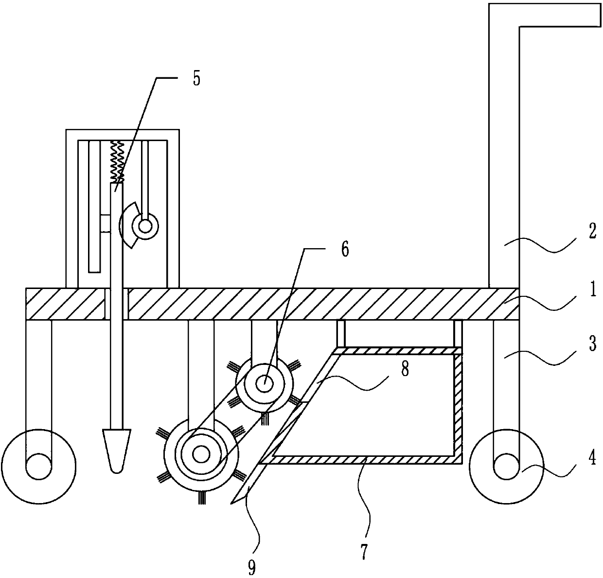
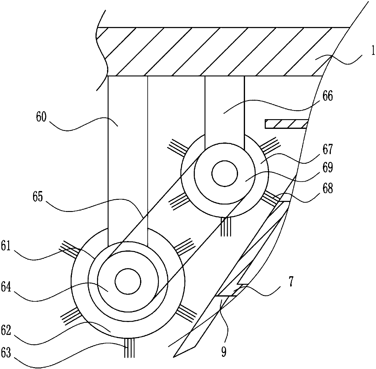
[0036] A ground cleaning device for engineering, including a bottom plate, a push handle, a wheel frame, wheels, a knocking device, a cleaning device, a collection box and a baffle, such as Figure 1-7 As shown, the top of the right side of the base plate 1 is provided with a push handle 2, the top of the left side of the base plate 1 is provided with a knocking device 5, the bottom of the base plate 1 is provided with a left-right symmetrical wheel frame 3, the bottom of the wheel frame 3 is equipped with wheels 4, and the bottom of the base plate 1 is on the right side. There is a collection box 7 on the side, the upper part of the left side of the collection box 7 is provided with a feed port 8, the left side of the bottom of the collection box 7 is provided with a baffle 9, and a cleaning device 6 is installed in the middle of the bottom of the bottom plate 1, and the cleaning device 6 is located on the left side of the collection box 7. side.

Embodiment 2

[0038] A ground cleaning device for engineering, including a bottom plate, a push handle, a wheel frame, wheels, a knocking device, a cleaning device, a collection box and a baffle, such as Figure 1-7 As shown, the top of the right side of the base plate 1 is provided with a push handle 2, the top of the left side of the base plate 1 is provided with a knocking device 5, the bottom of the base plate 1 is provided with a left-right symmetrical wheel frame 3, the bottom of the wheel frame 3 is equipped with wheels 4, and the bottom of the base plate 1 is on the right side. There is a collection box 7 on the side, the upper part of the left side of the collection box 7 is provided with a feed port 8, the left side of the bottom of the collection box 7 is provided with a baffle 9, and a cleaning device 6 is installed in the middle of the bottom of the bottom plate 1, and the cleaning device 6 is located on the left side of the collection box 7. side.

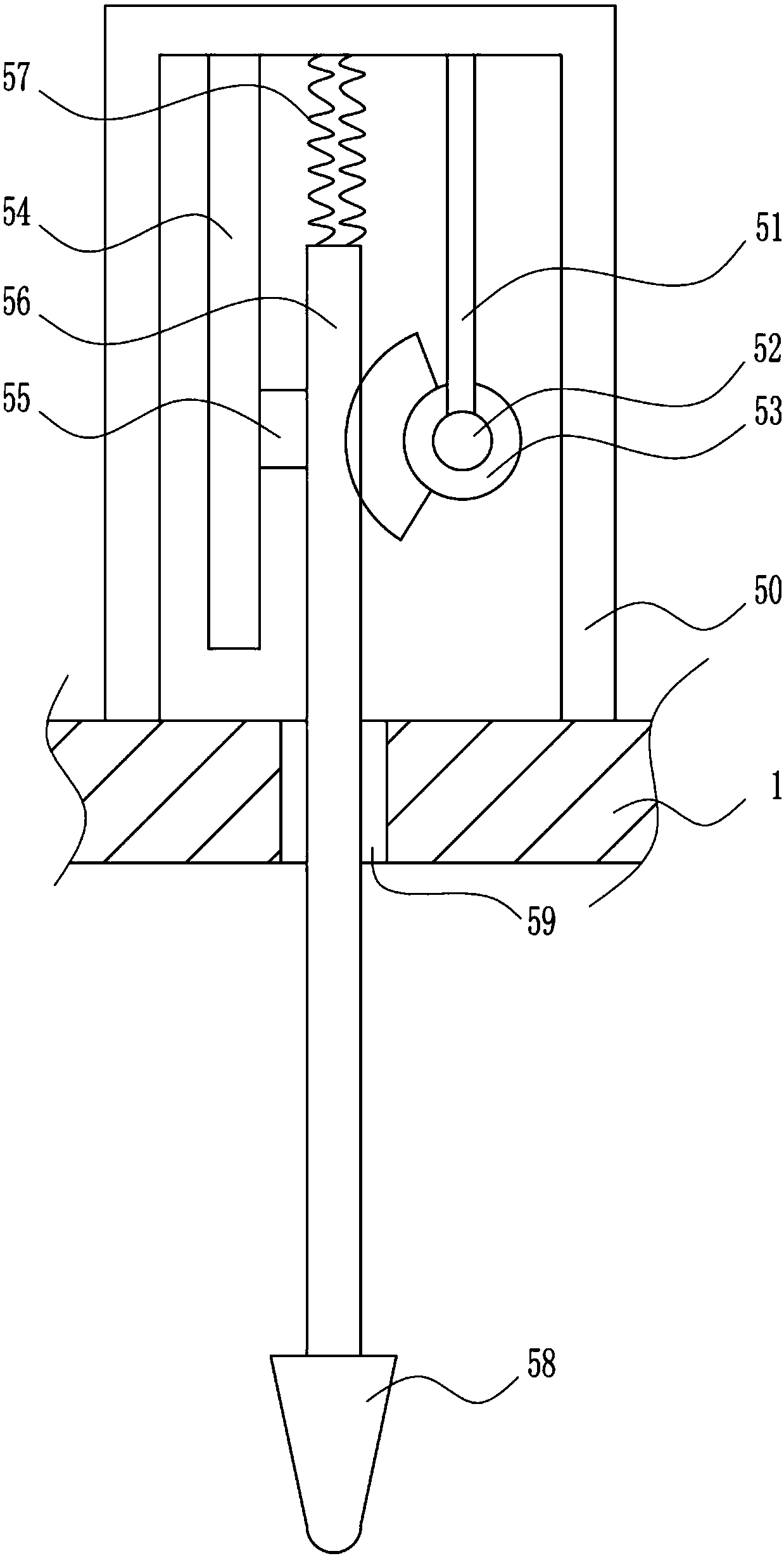
[0039] The knocking device ...

Embodiment 3

[0041] A ground cleaning device for engineering, including a bottom plate, a push handle, a wheel frame, wheels, a knocking device, a cleaning device, a collection box and a baffle, such as Figure 1-7 As shown, the top of the right side of the base plate 1 is provided with a push handle 2, the top of the left side of the base plate 1 is provided with a knocking device 5, the bottom of the base plate 1 is provided with a left-right symmetrical wheel frame 3, the bottom of the wheel frame 3 is equipped with wheels 4, and the bottom of the base plate 1 is on the right side. There is a collection box 7 on the side, the upper part of the left side of the collection box 7 is provided with a feed port 8, the left side of the bottom of the collection box 7 is provided with a baffle 9, and a cleaning device 6 is installed in the middle of the bottom of the bottom plate 1, and the cleaning device 6 is located on the left side of the collection box 7. side.

[0042] The knocking device ...


PUM

PropertyMeasurementUnit
Diameteraaaaaaaaaa

Abstract

The invention relates to a floor cleaning device, in particular to a floor cleaning device for engineering. The technical problem to be solved by the invention is to provide a floor cleaning device which has fast cleaning speed, clean sweeping and convenient movement for engineering. In order to solve the above technical problem, the invention provides such a floor cleaning device for engineeringwhich comprises a bottom plate, a pusher, a wheel carrier, a wheel, a percussion device, a sweeping device, a collection box and a baffle, wherein the pusher is arranged on the top of the right side of the bottom plate, the percussion device is arranged on the top of the left side of the bottom plate, the wheel carrier in bilateral symmetry is arranged at the bottom of the bottom plate, the wheelis arranged at the bottom of the wheel carrier, the collection box is arranged on the right side of the bottom of the bottom plate, a feeding inlet is formed in the upper part of the left side of thecollection box, and the baffle is arranged on the left side of the bottom of the collection box. The floor cleaning device for engineering achieves the effects of high cleaning speed, clean sweeping and convenient movement. The device adopts manual control of sweeping, so that the sweeping is cleaner, the sweeping speed is faster, the accuracy is high, and the operation is relatively simple.

Description

technical field [0001] The invention relates to a floor cleaning device, in particular to an engineering floor cleaning device. Background technique [0002] Construction engineering refers to the engineering entity formed through the construction of various housing buildings and their ancillary facilities and the installation activities of supporting lines, pipelines, and equipment. The ground mostly refers to the paving layer inside and around the building, and also refers to the floor Surface pavement. [0003] The ground cleaning machine is also called the floor washing machine. It is suitable for hard and weak floors such as cement, granite, marble, ceramics, slate, tiles, and wear-resistant floors in the cleaning work area. It is mainly divided into two types: hand push type floor cleaning machine and driving type floor cleaning machine. [0004] Existing engineering floor cleaning devices have disadvantages such as slow cleaning speed, unclean cleaning, and slow mov...

Claims


Application Information

Patent Timeline
IPC IPC(8): A47L11/24A47L11/40
CPCA47L11/24A47L11/4013A47L11/4036
Inventor 饶胜智张健润许荷东
Owner 饶胜智
Why Eureka
Try Eureka