Mechanism for transferring warp beam among textile workshops

A warp beam and workshop technology, applied in the field of warp beam transfer mechanism, can solve the problems of harming the health of workers, large warp beam size, time-consuming and labor-intensive problems, and achieves the advantages of convenient installation and transfer operation, low cost and long service life Effect

Pending Publication Date: 2018-03-27
SICHUAN YUYANG TEXTILE
View PDF10 Cites 1 Cited by
  • Summary
  • Abstract
  • Description
  • Claims
  • Application Information

AI Technical Summary

Problems solved by technology

[0002] A textile workshop generally includes a warping workshop, a sizing workshop, a weaving workshop, and a cloth inspection workshop. The yarn is processed through multiple processes to form a cloth, and the yarn is wound on the warp beam, which often needs to be transferred in each workshop. In order to process the process, the existing method is to use a warp beam trolley to transfer the warp beam, but the warp beam is often large in size and heavy in weight, and several workers often install the warp beam on the warp beam trolley by lifting , this process is time-consuming and labor-intensive, and it is relatively dangerous. If you do not pay attention to the warp beam slipping, it will hit the worker's feet and damage the health of the worker.

Method used


Image

  • Mechanism for transferring warp beam among textile workshops
  • Mechanism for transferring warp beam among textile workshops
  • Mechanism for transferring warp beam among textile workshops

Examples


Embodiment 1

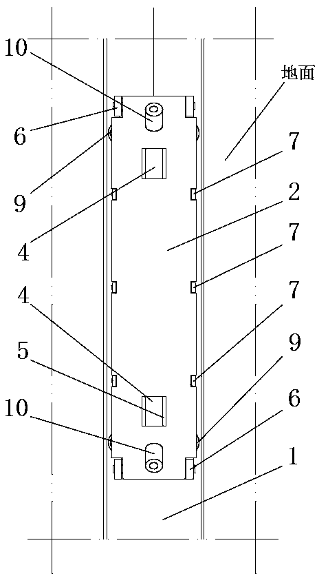
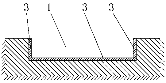
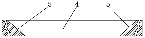
[0022] Such as figure 1 and 2 As shown, the warp beam 12 transfer mechanism between the textile workshops includes a rectangular track groove 1 set up on the floor of each workshop and a trolley arranged in the rectangular track groove 1. The rectangular track groove 1 communicates with each workshop, and the trolley includes a mounting plate 2 , the mounting plate 2 is made of steel, the mounting plate 2 is provided with rollers, so that the trolley can move along the rectangular track groove 1, the rolling wheels can be specifically set as rolling bearings, the upper surface of the mounting plate 2 is flush with the ground, and the length of the mounting plate 2 is greater than Warp beam 12 length, warp beam 12 can be installed on the mounting plate 2 by rolling from the side, further, the bottom and two sides of rectangular mounting groove are all fixedly provided with steel plate 3, the upper surface of side steel plate 3 is flush with the ground, lifts The compressive st...

Embodiment 2

[0027] Such as figure 1 and 2 As shown, on the basis of Embodiment 1, the front and rear ends of the left and right sides of the mounting plate 2 are all rotated to be provided with horizontal guide wheels 9, and the horizontal guide wheels 9 on both sides are symmetrical, and there are four horizontal guide wheels 9 in total. The rotation axis of guide wheel 9 is perpendicular to the ground, and horizontal guide wheel 9 is close to big roller 6, and the distance between the outer ends of both sides corresponding horizontal guide wheel 9 is greater than mounting plate 2 widths, makes the wheel surface of horizontal guide wheel 9 can be with The sides of the rectangular track groove 1 are in contact, and when the wheel surface of the horizontal guide wheel 9 can be in contact with the side of the rectangular track groove 1, the large roller 6 does not contact the side of the rectangular track groove 1. When the trolley advances, when the horizontal guide wheel When the wheel s...


PUM


Abstract

The invention relates to the technical field of warp beam transferring, in particular to a mechanism for transferring warp beam among textile workshops. The mechanism a rectangular rail groove in a floor of each workshop and a trolley in the rectangular rail groove, the rectangular rail groove is communicated with each workshop, the trolley comprises a mounting plate, rollers are arranged on the mounting plate to enable the trolley to move along the rectangular rail groove, the upper surface of the mounting plate is flush with the floor, the length of the mounting plate is larger than that ofeach warp beam, and each warp beam can be rolled from the lateral side to be mounted on the mounting plate. The mechanism is structurally simple and practical, convenient and quick in mounting and transferring operation, safe and reliable, quickness in mounting of the warp beams on the mechanism for transferring is realized, and labor intensity of workers is reduced.

Description

technical field [0001] The invention relates to the technical field of warp beam transfer, in particular to a warp beam transfer mechanism between textile workshops. Background technique [0002] A textile workshop generally includes a warping workshop, a sizing workshop, a weaving workshop, and a cloth inspection workshop. The yarn is processed through multiple processes to form a cloth, and the yarn is wound on the warp beam, which often needs to be transferred in each workshop. In order to process the process, the existing method is to use a warp beam trolley to transfer the warp beam, but the warp beam is often large in size and heavy in weight, and several workers often install the warp beam on the warp beam trolley by lifting , this process is time-consuming and laborious, and it is more dangerous. If you do not pay attention to the slipping of the warp beam, it will hit the worker's foot and damage the health of the worker. Contents of the invention [0003] The te...

Claims


Application Information

Patent Timeline
Patent Type & Authority Applications(China)
IPC IPC(8): B62B3/10
CPCB62B3/104B62B2202/025
Inventor 熊世清熊明清毛东军杨远明勾永安李秀芳陈果陈望
Owner SICHUAN YUYANG TEXTILE
Why Eureka
Try Eureka