Liquid soap bottle

A hand sanitizer and bottle body technology, applied in the field of hand sanitizer bottles, can solve the problems of waste of hand sanitizer, inconvenient use, difficulty in absorbing hand sanitizer, etc., and achieve the effect of deepening depth and reducing waste

Inactive Publication Date: 2018-03-27
陈庆寿
View PDF1 Cites 6 Cited by
  • Summary
  • Abstract
  • Description
  • Claims
  • Application Information

AI Technical Summary

Problems solved by technology

[0002] The traditional hand sanitizer bottle has the following problems, the suction tube extends vertically downward into the bottle, and there is a certain gap with the bottom of the bottle, but in the final stage of use, the suction tube is difficult to suck into the bottle. Hand sanitizer, causing inconvenience and waste of hand sanitizer
In order to solve the above problems, the invention with patent application number 201510177889.5 discloses a hand sanitizer bottle, which includes a bottle body, a liquid pressing mechanism and a suction tube arranged in the bottle; At the liquid outlet; the shape of the pipette is S-shaped; the material of the pipette is polypropylene, and it is hoped that the liquid in the hand sanitizer bottle can be easily sucked up by the S-shaped pipette, but The self-tension of the suction tube will press the lotion port of the suction tube to the bottom of the bottle, so that the hand sanitizer cannot be sucked in.

Method used


Image

  • Liquid soap bottle
  • Liquid soap bottle

Examples


Embodiment 1

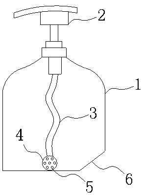
[0015] Such as figure 1 As shown, the hand sanitizer bottle of the present embodiment includes a bottle body 1, a pressing liquid outlet mechanism 2 and a liquid suction pipe 3 arranged in the bottle body 1; The key point is that the suction pipe 3 is made of flexible material, and the bottom end of the suction pipe 3 is provided with a load-bearing part 4 made of a heavier material (density greater than that of hand sanitizer). The liquid port 5 is located at the load-bearing part 4; one side of the bottom of the bottle is provided with an inclined plane 6, and the length of the pipette 3 is equal to the distance from the top of the pipette 3 to the inclined plane 6.

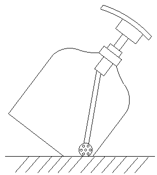
[0016] The load-bearing part 4 will sink to the bottom of the hand sanitizer bottle under its own gravity, so it can ensure that the hand sanitizer at the bottom of the bottle is sucked; The depth behind the bottom is relatively shallow, even if the liquid suction port 5 is brought to the bottom of the bottle ...


PUM


Abstract

The invention aims to provide a liquid soap bottle. By adoption of the liquid soap bottle, liquid soap can be conveniently sucked out as much as possible, and waste of the liquid soap is reduced. Theliquid soap bottle comprises a bottle body, a pressing liquid outlet mechanism and a liquid suction pipe arranged inside the bottle body. The pressing liquid outlet mechanism is arranged at a liquid outlet of the liquid suction pipe. The liquid soap bottle is characterized in that the liquid suction pipe is made of a flexible material, and a load-bearing part is arranged at the bottom end of the liquid suction pipe; a liquid suction opening of the liquid suction pipe is located in the load-bearing part; and the length of the liquid suction pipe is larger than or equal to the distance from thetop end of the liquid suction pipe to any side of the bottom of the bottle body. At the last using stage, due to the small amount of the liquid soap, the depth of the liquid soap is small after the liquid soap is flatly laid at the bottle bottom. At the moment, the bottle body can be tilted, the liquid soap remaining inside the bottle can be gathered to one corner of the bottom of the bottle body,and therefore the depth of the liquid soap can be increased, the load-bearing part carries the liquid suction opening to be sunken into the bottom of the liquid soap automatically so as to suck the liquid soap, the liquid soap can be sucked as much as possible, and waste is reduced.

Description

technical field [0001] The invention relates to a hand sanitizer bottle. Background technique [0002] The traditional hand sanitizer bottle has the following problems, the suction tube extends vertically downward into the bottle, and there is a certain gap with the bottom of the bottle, but in the final stage of use, the suction tube is difficult to suck into the bottle. Hand sanitizer, has caused the waste of inconvenience and hand sanitizer. In order to solve the above problems, the invention with patent application number 201510177889.5 discloses a hand sanitizer bottle, which includes a bottle body, a liquid pressing mechanism and a suction tube arranged in the bottle; At the liquid outlet; the shape of the pipette is S-shaped; the material of the pipette is polypropylene, and it is hoped that the liquid in the hand sanitizer bottle can be easily sucked up by the S-shaped pipette, but The self-tension of the pipette will press the liquid mouth of the pipette against t...

Claims


Application Information

Patent Timeline
Patent Type & Authority Applications(China)
IPC IPC(8): B65D47/34
CPCB05B11/1095
Inventor 陈庆寿黄华
Owner 陈庆寿
Why Eureka
Try Eureka