Broadband Doherty power amplifier

A technology for power amplifiers and amplifiers, applied in power amplifiers, amplifiers, high-frequency amplifiers, etc., can solve the problems of limited bandwidth of wavelength transmission lines, unfavorable design of broadband amplifiers, and difficult chip implementation.

Pending Publication Date: 2022-03-01
LANSUS TECH INC
View PDF0 Cites 7 Cited by
  • Summary
  • Abstract
  • Description
  • Claims
  • Application Information

AI Technical Summary

Problems solved by technology

[0004] However, for the Doherty power amplifier of the related art, for the monolithic microwave integrated circuit, the power divider and the quarter-wavelength transmission line of the traditional Doherty power amplifier are all too large in size and difficult to realize on the chip.
At the same time, the bandwidth of the quarter-wavelength transmission line is limited, which is very unfavorable for the design of broadband amplifiers

Method used


Image

  • Broadband Doherty power amplifier
  • Broadband Doherty power amplifier
  • Broadband Doherty power amplifier

Examples


Embodiment 1

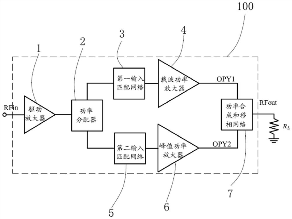
[0045] An embodiment of the present invention provides a broadband Doherty power amplifier 100 .

[0046] The broadband Doherty power amplifier 100 includes a driver amplifier 1 , a power divider 2 , a first input matching network 3 , a carrier power amplifier 4 , a second input matching network 5 , a peak power amplifier 6 and a power combining and phase shifting network 7 .

[0047] specific:

[0048] The drive amplifier 1 is used to amplify the signal input from the outside.

[0049] The power splitter 2 is used for splitting the amplified signal of the drive amplifier 1 into two output paths and realizing non-uniform distribution of power.

[0050] The first input matching network 3 is used to realize -90 degree phase shift and impedance matching of the received signal.

[0051] The carrier power amplifier 4 is used to amplify the received signal.

[0052] The second input matching network 5 is used to achieve 0-degree phase shift and impedance matching for the received...

Embodiment 2

[0092] Embodiment 2 provides a broadband Doherty power amplifier 200 . Please refer to Figure 5 as shown, Figure 5 A schematic structural diagram of an application circuit of Embodiment 2 of the broadband Doherty power amplifier 200 provided by the embodiment of the present invention.

[0093] The circuit structure of the wideband Doherty power amplifier 200 is basically the same as that of the wideband Doherty power amplifier 100 . The difference between the circuit structure of the broadband Doherty power amplifier 200 and the broadband Doherty power amplifier 100 is:

[0094]The first input matching network 3 also includes a first phase-modulating inductor La. Specifically, the first phase-modulating inductor La is connected between the first end of the seventh capacitor C7 and the ground GND. That is, the circuit connection relationship is: the first end of the first phase-modulating inductor La is connected to the first end of the seventh capacitor C7, and the seco...


PUM


Abstract

The invention provides a broadband Doherty power amplifier. The broadband Doherty power amplifier comprises a driving amplifier, a power divider, a first input matching network, a carrier power amplifier, a second input matching network, a peak power amplifier and a power synthesis and phase shift network, the first input matching network is used for performing-90-degree phase shift and impedance matching on the received signal; the second input matching network is used for realizing 0-degree phase shift and impedance matching of the received signal; the power synthesis and phase shift network is used for synthesizing the power of the two paths of output signals to realize 90-degree phase shift and impedance matching and then outputting the signals to an external system load; the power synthesis and phase shift network comprises a Balun impedance transformer, a first matching capacitor, a second matching capacitor, a third matching capacitor, a fourth matching capacitor, a fifth matching capacitor, a fourteenth inductor and a fifteenth inductor. The broadband Doherty power amplifier is wide in working frequency band, small in layout area, high in power additional efficiency and high in linearity of output power.

Description

technical field [0001] The invention relates to the field of circuit technology, in particular to a wideband Doherty power amplifier. Background technique [0002] In order to make full use of spectrum resources and increase the data transmission rate in modern wireless communication systems, the peak-to-average ratio (PAPR) signal format is adopted for modulation signals. High peak-to-average ratio signals impose strict requirements on the linearity of RF power amplifiers. In order to ensure the undistorted transmission of the signal, the wireless communication system requires the RF power amplifier to work in a power back-off state far away from the power compression point, so as to ensure the linear amplification of the RF signal. However, RF power amplifiers are often designed for a fixed power supply voltage, the load impedance is optimized at the maximum output power, and the efficiency is very low when the power is backed off. In order to improve the efficiency of R...

Claims


Application Information

Patent Timeline
Patent Type & Authority Applications(China)
IPC IPC(8): H03F1/02H03F1/32H03F1/56H03F3/19H03F3/21
CPCH03F1/0288H03F1/32H03F1/565H03F3/19H03F3/21H03F2200/451
Inventor 彭艳军宣凯郭嘉帅
Owner LANSUS TECH INC
Why Eureka
Try Eureka