Electromagnetic control valve
A technology of electromagnetic control valve and valve core, applied in valve details, valve device, valve operation/release device, etc., can solve the problems of complex control circuit, large coil heating, high coil power consumption, etc., to simplify the control circuit, The effect of reducing power consumption and heat generation, and reducing the failure rate
- Summary
- Abstract
- Description
- Claims
- Application Information
AI Technical Summary
Problems solved by technology
Method used
Image

Examples
Embodiment 1
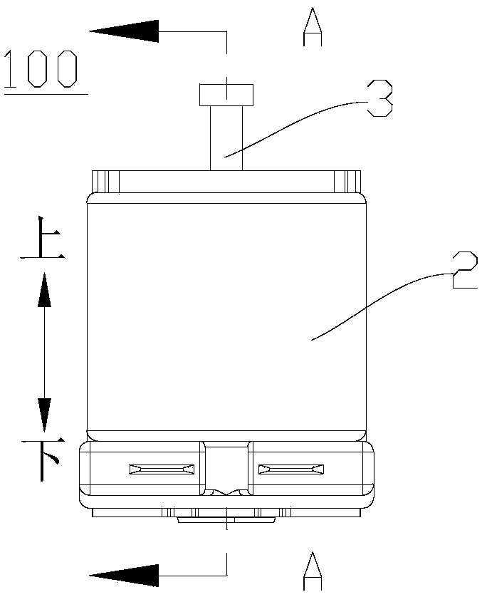
[0083] Such as Figure 1-Figure 10 As shown, the electromagnetic control valve 100 in this embodiment is an electromagnetic actuator, and the electromagnetic control valve is a normally open electromagnetic control valve.
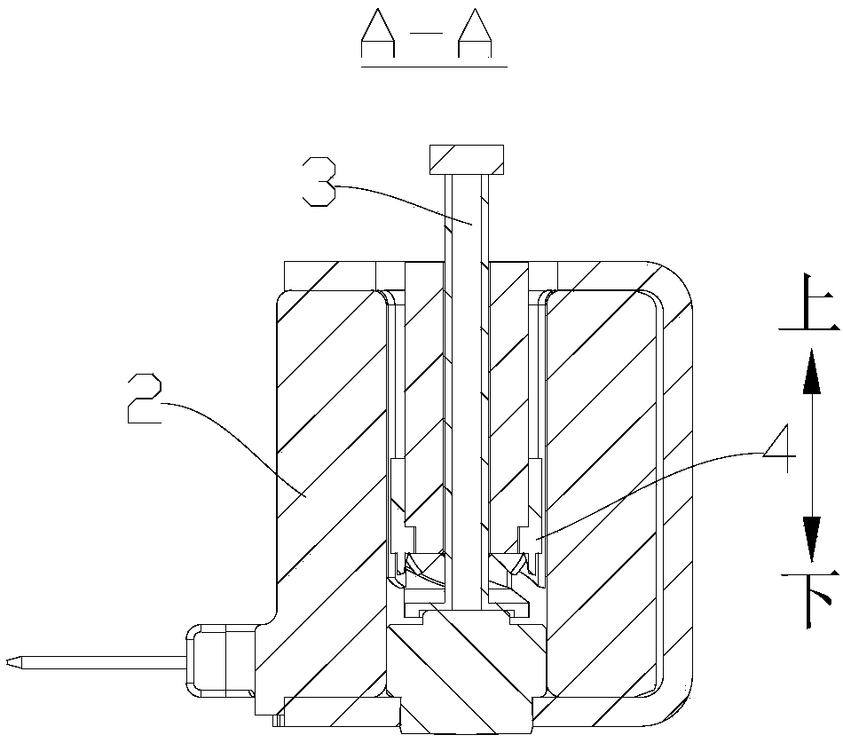
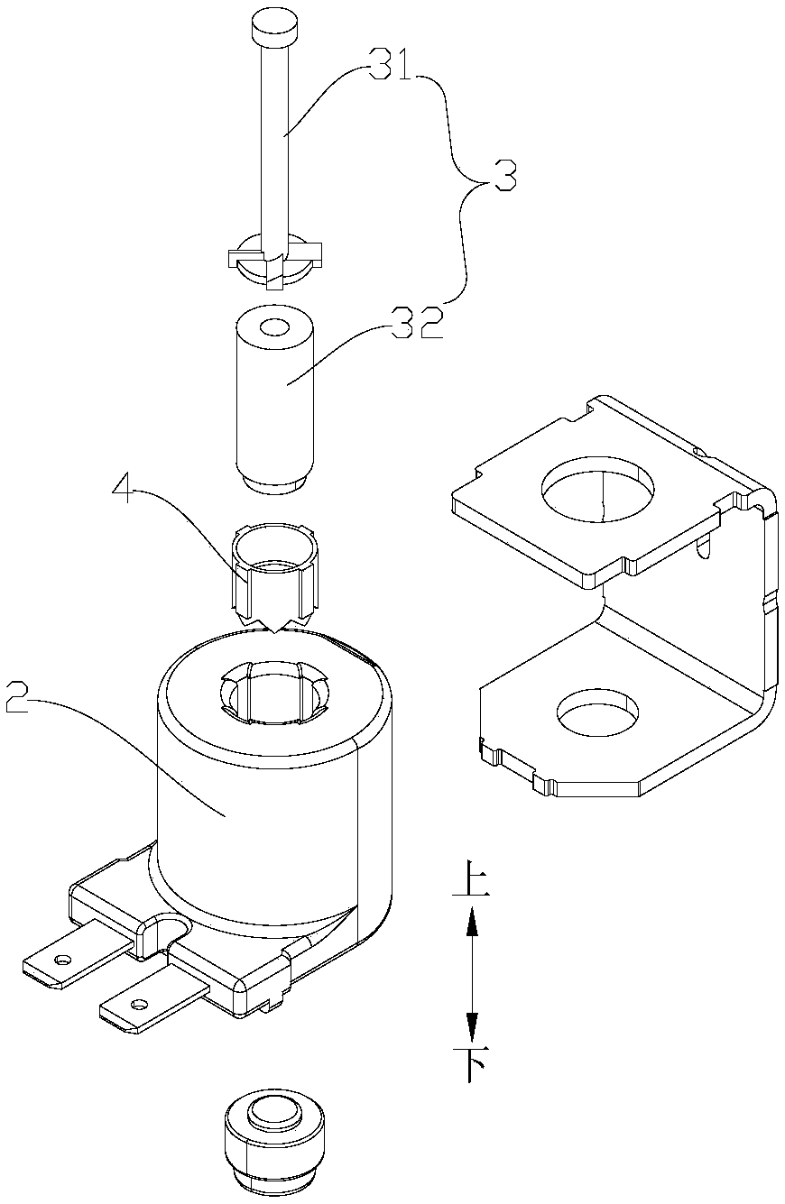
[0084] Such as Figure 1-Figure 10 As shown, the electromagnetic control valve 100 of this embodiment may include a valve core guide sleeve 1 , a coil assembly 2 , a control part 5 , a movable valve core 3 , a fixed iron core and a movable part 4 . Wherein, the coil assembly 2 is sheathed on the outside of the valve core guide sleeve 1 and the valve core guide sleeve 1 and the coil assembly 2 are fixed together.
[0085] Specifically, such as Figure 5-Figure 6 As shown, the spool guide sleeve 1 defines a moving cavity 11 with an opening, and the inner peripheral wall of the moving cavity 11 is provided with a matching protrusion 111, and the matching protrusion 111 is provided with a hole that runs through it in the axial direction, that is, in the up an...
Embodiment 2
[0096] Such as Figure 11-Figure 19 As shown, the electromagnetic control valve 100 in this embodiment is an electromagnetic valve, and the electromagnetic control valve 100 is a normally open electromagnetic control valve.
[0097] Such as Figure 11-Figure 19 As shown, the electromagnetic control valve 100 of this embodiment may include a valve core guide sleeve 1 , a coil assembly 2 , a control part 5 , a movable valve core 3 and a movable part 4 . Wherein, the coil assembly 2 is sheathed on the outside of the valve core guide sleeve 1 .
[0098] Specifically, such as Figure 5-Figure 6 As shown, the spool guide sleeve 1 defines a moving cavity 11 with an opening, and the inner peripheral wall of the moving cavity 11 is provided with a matching protrusion 111, and the matching protrusion 111 is provided with a hole that runs through it in the axial direction, that is, in the up and down direction. Move slot 1111. An end surface of the fitting protrusion 111 away from th...
PUM
 Abstract
Description
Claims
Application Information
 - R&D Engineer
- R&D Manager
- IP Professional
- Industry Leading Data Capabilities
- Powerful AI technology
- Patent DNA Extraction
Browse by: Latest US Patents, China's latest patents, Technical Efficacy Thesaurus, Application Domain, Technology Topic.
© 2024 PatSnap. All rights reserved.Legal|Privacy policy|Modern Slavery Act Transparency Statement|Sitemap