
A multi-layer cmy color mixing system and optical path system

A technology of color mixing and color mixing unit, which is applied in the direction of electric light source, fixed light source, and optical elements used to change the spectral characteristics of emitted light, etc. It can solve the problems of inconvenient stage art design and slow cutting in and out speed of a single color mixing chip. achieve fast results

Active Publication Date: 2020-06-19
GUANGZHOU HAOYANG ELECTRONICS CO LTD
View PDF6 Cites 0 Cited by
  • Summary
  • Abstract
  • Description
  • Claims
  • Application Information

AI Technical Summary

Problems solved by technology

[0003] The color mixing component used in the existing stage lighting technology is a single-chip color-mixing piece that cuts into the vertical cross section of the light column from one side until the entire vertical cross-section of the light column is completely cut in. Different color mixing effects are sometimes required during stage performances, which requires multiple stage lights with different color mixing effects to achieve, which brings great inconvenience to stage art design

Method used


Image

  • A multi-layer cmy color mixing system and optical path system
  • A multi-layer cmy color mixing system and optical path system
  • A multi-layer cmy color mixing system and optical path system

Examples


Embodiment 1

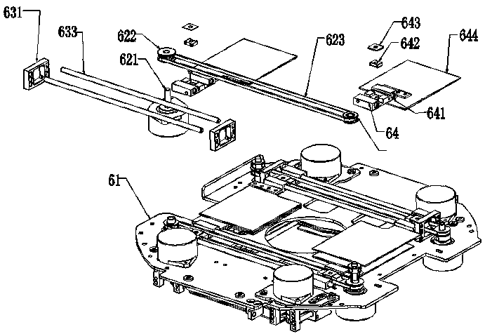
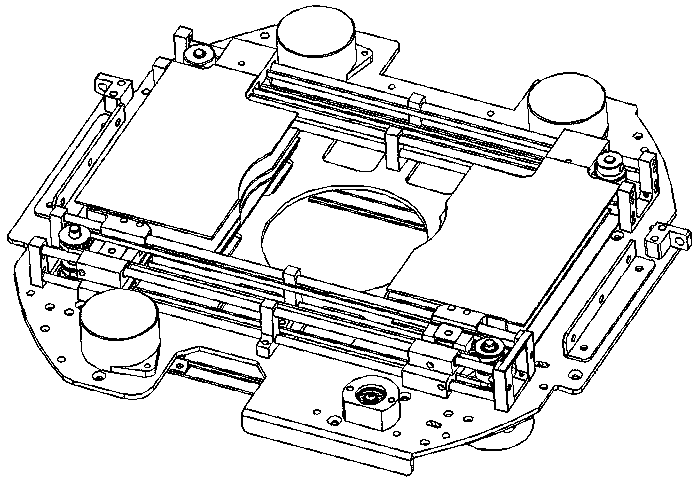
[0030] A schematic diagram of a multi-layer CMY color mixing system in this embodiment is as follows Figure 1 to Figure 2 As shown, it includes a CMY fixed frame 61 and a multi-layer color mixing unit fixed thereon. The CMY fixed frame 61 is provided with a through hole; each layer of color mixing unit includes two motion units, and each motion unit includes a CMY motion assembly 64, a fixed The CMY color mixing sheet 644 on the CMY moving assembly 64 and the driving device that drives the CMY moving assembly 64 to move; the two driving devices drive the CMY moving assembly 64 to move toward each other so that the corresponding two CMY color mixing sheets 644 are closed on the through hole. Light.

[0031] When using the multi-layer CMY color mixing system 6, install it on the stage lamp, and make the through hole face the exit direction of the light source 2; when the color mixing effect is required, control the two driving devices to drive the CMY moving assembly 64 to move t...

Embodiment 2

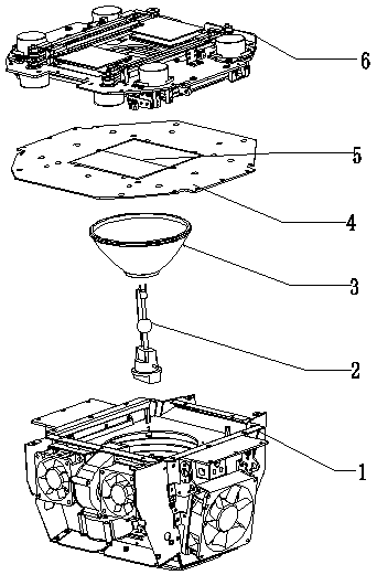
[0046] This embodiment provides an optical path system, the schematic diagram of which is shown in image 3 As shown, it includes any one of the above two multi-layer CMY color mixing systems 6, and the lamp holder system fixing frame 4, reflective cup 3, light source 2 and fixing seat 1 which are sequentially arranged under the multi-layer CMY color mixing system 6; The cup 3 and the light source 2 are fixed in the fixed seat 1, and the fixed seat 1 is provided with a heat dissipation system. The fixed seat 1 is fixed on the lamp holder system fixing frame 4, and the lamp holder system fixing frame 4 is provided with a heat insulating sheet 5.

[0047] The optical path system of the invention has multiple color mixing effects and brings convenience to stage art design.


PUM


Abstract

A multi-layer CMY colour mixing system, comprising a CMY fixing frame (61) and a plurality of colour mixing unit layers fixed thereon, the CMY fixing frame (61) being provided with a through hole, each colour mixing unit layer comprising two movement units, each movement unit comprising a CMY movement assembly (64), a CMY colour mixing sheet (644) fixed on the CMY movement assembly (64) and a drive apparatus which drives the CMY movement assembly (64) to move, the two drive apparatuses respectively driving the CMY movement assemblies (64) to move towards one another so that the two corresponding CMY colour mixing sheets (644) close on the through hole to perform light adjustment. When used specifically, one or more colour mixing unit layers may be controlled to move so as to achieve colour mixing effects. Also disclosed is a light path system which includes the multi-layer CMY colour mixing system. The colour mixing sheets have rapid cut-in and cut-out speeds, provide a variety of colour mixing effects when mounted on a stage light, and thereby facilitate stage design.

Description

technical field [0001] The present invention relates to the technical field of optical equipment, and more specifically, to a multilayer CMY color mixing system and an optical path system. Background technique [0002] In order to enrich the stage art effect and enhance the atmosphere, various effect components are often added to the optical system of the stage light to obtain various lighting effects, such as color wheel components, pattern components, color mixing components, etc., where the color mixing components are driven by driving the color mixing film to move To the position of the vertical cross-section of the light column to obtain a mixed-color beam to render the stage background and enhance the atmosphere of the scene. [0003] The color mixing component used in the existing stage lighting technology is a single-chip color-mixing piece that cuts into the vertical cross section of the light column from one side until the entire vertical cross-section of the light...

Claims


Application Information

Patent Timeline
Patent Type & Authority Patents(China)
IPC IPC(8): F21S10/02F21V9/40F21V14/00F21W131/105F21W131/406
CPCF21S10/026F21V14/006F21W2131/105F21W2131/406
Inventor 蒋伟楷其他发明人请求不公开姓名
Owner GUANGZHOU HAOYANG ELECTRONICS CO LTD
Learn More