
Jet-flow type gas sensation system applicable to security examination and method

A sensing system and safety inspection technology, applied in the analysis of gas mixtures, the structural details of gas analyzers, sampling, etc., can solve the problems of loss of life and property, limited measurement range, unreasonable flow field organization, etc., to achieve high reliability, The effect of increasing the firing range and increasing the amount of gas trapped

Pending Publication Date: 2018-03-27
NANJING UNIV OF AERONAUTICS & ASTRONAUTICS
View PDF10 Cites 1 Cited by
  • Summary
  • Abstract
  • Description
  • Claims
  • Application Information

AI Technical Summary

Problems solved by technology

In order to prevent criminals from bringing flammable and explosive gas (liquid) or toxic and harmful gases into these places, it is necessary to carry out safety monitoring on the personnel entering these places to prevent toxic and harmful gases or liquids from causing safety accidents and causing huge damage to people's lives and property. loss
[0003] Installing gas detectors in densely populated places is beneficial to the investigation of people carrying toxic and harmful gases or liquids. However, most gas detectors on the market can only detect at fixed points, and the measurement range is limited. A few gas detectors are equipped with air supply and Air induction device, but the flow field organization is unreasonable, the mixed gas carrying toxic and harmful gases cannot enter the detection end, which affects the reliability of gas detection, so it is necessary to design a gas detection device with reasonable air supply mode and high detection reliability

Method used


Image

  • Jet-flow type gas sensation system applicable to security examination and method
  • Jet-flow type gas sensation system applicable to security examination and method
  • Jet-flow type gas sensation system applicable to security examination and method

Examples


Embodiment Construction

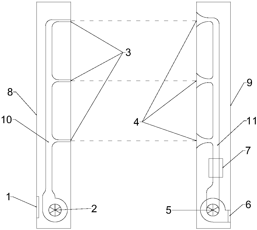
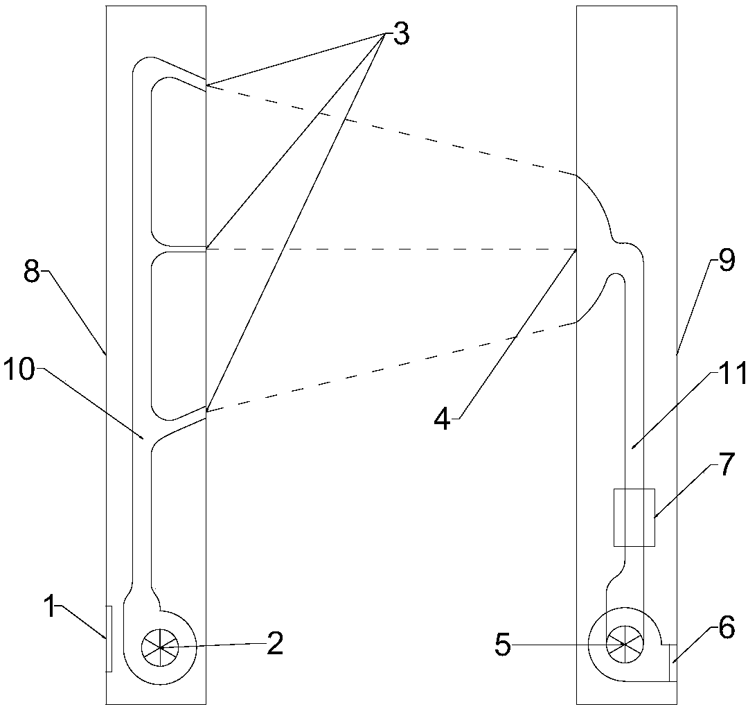
[0024] Attached below figure 1 And attached figure 2 Introduces the working method of the jet fan and suction gas induction system suitable for safety inspection: under the action of the blower 2, the gas is ejected through the jet nozzle 3 arranged on the air supply pipe 10, driving the air supply column 8 and the gas The gas in the middle of the detection column 9 flows to the gas capture port 4 together. When the gas reaches the vicinity of the capture port 4, it is sucked into the gas detector 7 by the induced draft fan 5, and then passes through the induced draft fan 5 from the bottom of the gas detection column 9. The air outlet 6 discharges, and when the gas to be detected is contained in the gas between the air supply column and the gas detection column, the gas detector 7 sends out an audible and visual alarm.

[0025] A special jet nozzle is installed on the air pipe on the air supply column, which not only improves the air supply range, but also ensures that the g...


PUM


Abstract

The invention discloses a jet-flow type gas sensation system applicable to security examination and a method and belongs to the field of gas detection. The system mainly comprises two parts, namely anair supply column and a gas detection column. The system is characterized in that under the action of an air supply machine, a gas is ejected out through a jet-flow nozzle arranged on an air supply tube; the gas between the air supply column and the gas detection column is driven to flow to a gas capturing hole together with the air; when being close to the gas capturing hole, the gas is sucked by a draft fan and is fed into a gas detector and is further discharged out from the bottom end of the gas detection column; and if the gas between the air supply column and the gas detection column comprises a gas to be detected, a sound-light alarm can be made by the gas detector. Due to adoption of the special jet-flow nozzle mounted on the air supply column of the system, a large jet-flow distance, intense gas mixing and high reliability of a gas supply system are ensured, and the system is applicable to detection on dangerous gases in automobile stations, subway stations, high-speed rail stations, airports and other densely populated places.

Description

technical field [0001] The invention designs a jet-type gas induction system suitable for safety inspection, which belongs to the field of gas detection. Background technique [0002] Stations, subway stations, high-speed rail stations, airports, theaters and other places have a large population mobility and dense population, and these places have higher requirements for safety monitoring. In order to prevent criminals from bringing flammable and explosive gas (liquid) or toxic and harmful gases into these places, it is necessary to carry out safety monitoring on the personnel entering these places to prevent toxic and harmful gases or liquids from causing safety accidents and causing huge damage to people's lives and property. loss. [0003] Installing gas detectors in densely populated places is beneficial to the investigation of people carrying toxic and harmful gases or liquids. However, most gas detectors on the market can only detect at fixed points, and the measureme...

Claims


Application Information

Patent Timeline
Patent Type & Authority Applications(China)
IPC IPC(8): G01N1/24G01N33/00
CPCG01N1/24G01N33/0009G01N2001/242
Inventor 黄岭韩东郑明瑞王景炎宋岩
Owner NANJING UNIV OF AERONAUTICS & ASTRONAUTICS
Learn More