
Diluted Ubbelohde viscometer

A Ubbelohde viscometer and scale technology, which is applied in viscometer maintenance, flow characteristics, measuring devices, etc., can solve the problems of inconvenient liquid addition, large measurement error, uneven stirring, etc., and achieve easy operation, long service life, The effect of convenient production and implementation

Inactive Publication Date: 2018-03-27
杭州震越科技有限公司
View PDF8 Cites 2 Cited by
  • Summary
  • Abstract
  • Description
  • Claims
  • Application Information

AI Technical Summary

Problems solved by technology

[0003] The present invention aims at the shortcomings of the prior art, such as inconvenient cleaning, large measurement errors, waste of reagents, etc., inconvenient liquid addition and uneven stirring during the dilution and sample addition process, and provides a dilution Ubbelohde viscometer and a measuring device and Measurement methods

Method used


Image

  • Diluted Ubbelohde viscometer
  • Diluted Ubbelohde viscometer

Examples


Embodiment 1

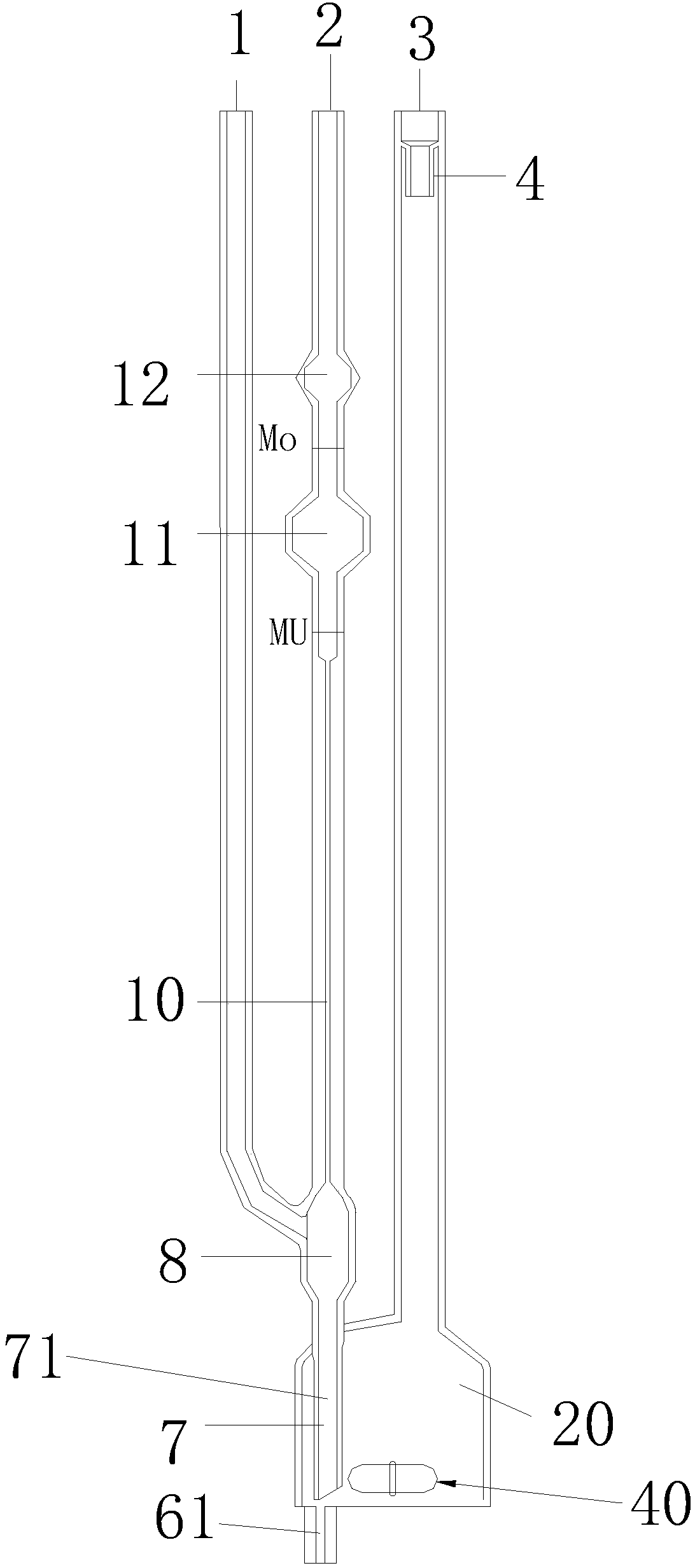
[0032] Such as figure 1 As shown, a diluted Ubbelohde viscometer includes a pumping liquid pipe 3 and a measuring pipe 2. One side of the measuring pipe 2 is connected with a vent pipe 1, and the lower end of the measuring pipe 2 is connected with a liquid inlet and discharge pipe 7. The bottom of the liquid pipe 3 is connected with a mixing ball 6 , the inlet and outlet pipe 7 is inserted into the bottom of the mixing ball 20 , and the lower end of the mixing ball 6 is connected with a raw liquid inlet pipe 61 . The bottom of the mixing ball 20 is a plane; the bottom of the cavity of the mixing ball 20 is provided with a magnetic stirrer 40 . A magnetic stirrer is provided on the outside of the corresponding mixing ball 20 to act on the magnetic stirrer 40 so that it can rotate and stir the mixed liquid. For easy understanding, the inlet and outlet pipe 7 is provided with an inlet and outlet channel 71 , and the inlet and outlet channel 71 is directly inserted into the botto...

Embodiment 2

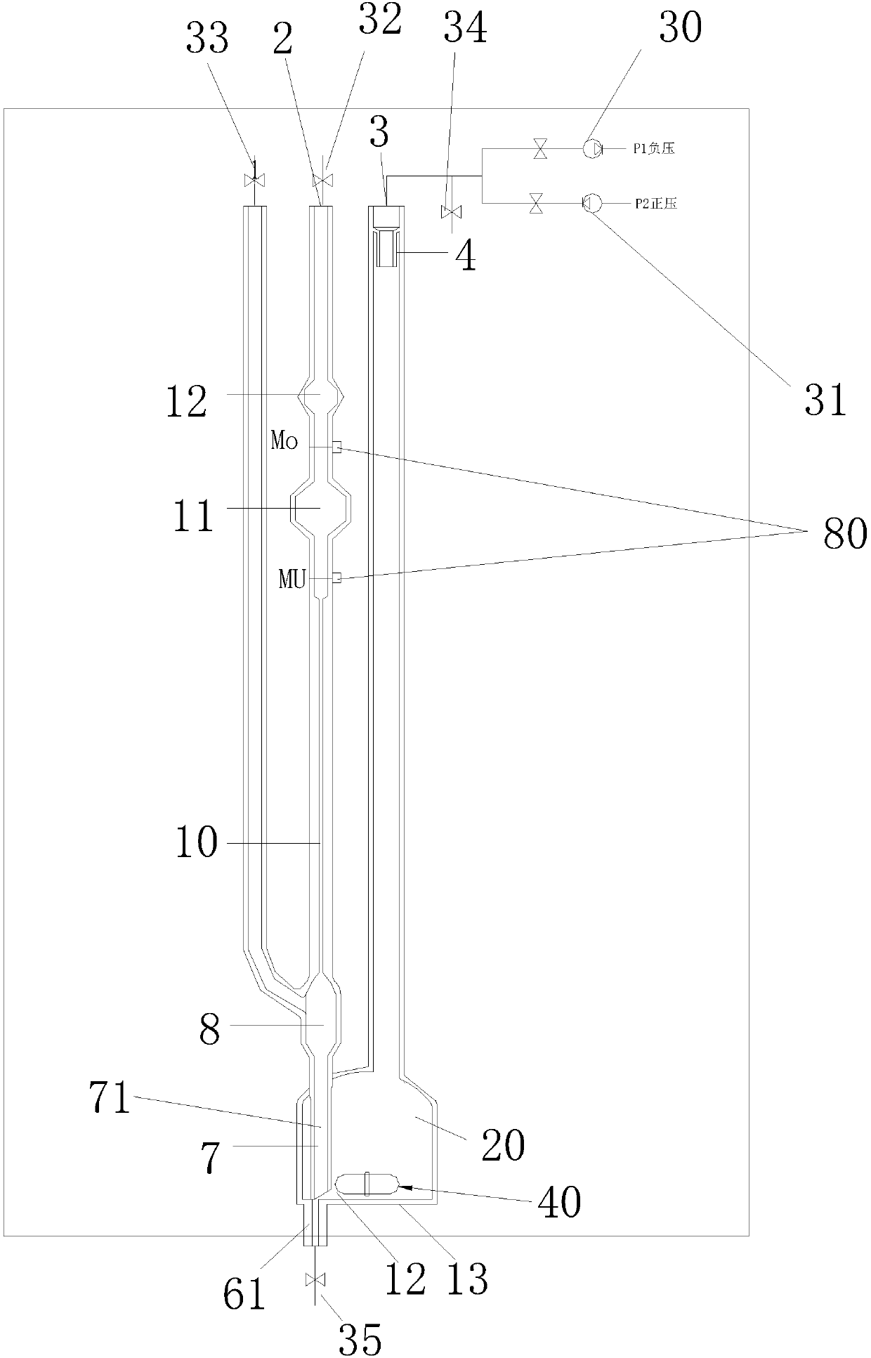
[0046] Such as figure 1 and figure 2 As shown, a fully automatic dilution viscometer includes the dilution Ubbelohde viscometer described in Example 1, the dilution Ubbelohde viscometer is arranged in an installation box 50, and the installation box 50 is a constant temperature box. The upper timing scale MO and the lower timing scale MU are provided with sensors, and in order to realize automation, the device also includes a controller. The first switch device 32, the second switch device 33, the third switch device 34 and the fourth switch device 35 are electromagnetic switch valves, which are connected with the controller line, and the liquid pumping device 30 and the liquid pushing device 31 are connected with the controller line; The liquid device 30 is a vacuum pump, and the liquid pushing device 31 is a booster pump.

[0047]The present invention also provides a measurement method utilizing the fully automatic dilution viscosity measuring device; comprising the follo...


PUM


Abstract

The invention relates to the field of viscometers and discloses a diluted Ubbelohde viscometer. The viscometer comprises a liquid suction / discharge pipe (3) and a measuring tube (2). One side of the measuring tube (2) is connected to an escape pipe (1). The lower end of the measuring tube (2) is connected to a liquid feeding / discharge pipe (7). A mixing ball (6) is connected to the lower part of the liquid suction / discharge pipe (3). The liquid feeding / discharge pipe (7) is inserted into the bottom of the mixing ball (6). The lower end of the mixing ball (6) is connected to a raw liquid inletpipe (61). The opening of the liquid suction / discharge pipe (3) is connected to a liquid suction device (30) and a liquid pushing device (31). The measuring tube (2), the escape pipe (1), the liquid suction / discharge pipe (3) and the raw liquid inlet pipe (61) are connected to switches for controlling pipe opening sealing. The diluted Ubbelohde viscometer realizes convenient sample feeding, has uniform stirring effects, produces accurate measurement results, is cleaned through simple processes and has a high recovery rate of the sample solution and the cleaning solution.

Description

technical field [0001] The invention relates to the field of viscometers, in particular to a diluted Ubbelohde viscometer. Background technique [0002] The Ubbelohde viscometer is mainly used to measure the kinematic viscosity of the liquid. It is a gravity-type capillary viscometer. Compared with the viscometer, the liquid storage ball of the sample is designed at the bottom, and the bottom is designed to be flat, and the automatic sampling tube is added to realize the fully automatic sampling, stirring, measurement, cleaning, etc. of the diluted viscometer. Monopoly. Traditional diluters are not fully automated at present in China. Traditional sample addition, stirring and measurement are all done manually, and the measured data has large errors, takes a long time, and consumes a lot of chemical solvents for cleaning, polluting the environment. Contents of the invention [0003] The present invention aims at the shortcomings of the prior art, such as inconvenient clea...

Claims


Application Information

Patent Timeline
IPC IPC(8): G01N11/06G01N11/00
CPCG01N11/00G01N11/06G01N2011/0006
Inventor 王震库
Owner 杭州震越科技有限公司
Learn More